Beamforming to a subset of receive antennas in a wireless MIMO communication system

a wireless communication system and subset of receive antennas technology, applied in the field of beamforming while, can solve the problems of significant increase in system complexity and processing overhead, significant increase in processing overhead of the transmission system, and increase in the calculation and processing overhead associated with computing the beamsteering coefficient or the steering matrix. the effect of beamforming speed, reducing processing overhead

Active Publication Date: 2010-08-31
NXP USA INC
View PDF6 Cites 72 Cited by
  • Summary
  • Abstract
  • Description
  • Claims
  • Application Information

AI Technical Summary

Benefits of technology

[0013]A beamforming technique used in a MIMO wireless transmission system determines a beamforming steering matrix based on a subset (i.e., less than all) of the receiver antennas within the communication system, to thereby increase the speed and / or to decrease the processing needed to implement effective beamforming within the communication system. While this beamforming technique may not provide the best possible reception obtainable in the communication system, this technique can provide increased performance over no beamforming without significantly increasing the processing overhead of the transmission system, especially when a large number of receiver antennas are present within the system. This beamforming technique can additionally be used when a transmitter, with multiple transmitter antennas, is used to communicate with multiple receivers, each of which includes one or more receiver antennas. In this case, the beamforming technique may select a subset of the receiver antennas that includes, for example, at least one receiver antenna from each of the receivers and may then beamform to the selected subset of receiver antennas.

Problems solved by technology

While it is known to perform beamforming in a MIMO system in a mariner that creates a beam pattern optimized with respect to all of the receiver antennas in the MIMO system or at least to all of the available receiver antennas, which thereby maximizes transmission reliability, the calculations and processing overhead associated with computing the beamsteering coefficients or the steering matrix increase significantly as the number of transmission and receiver antennas increases.
As a result, beamforming in a MIMO system may significantly increase the system complexity and processing overhead when a large number of transmission and receiver antennas are present.
While this beamforming technique may not provide the best possible reception obtainable in the communication system, this technique can provide increased performance over no beamforming without significantly increasing the processing overhead of the transmission system, especially when a large number of receiver antennas are present within the system.

Method used


Image

  • Beamforming to a subset of receive antennas in a wireless MIMO communication system
  • Beamforming to a subset of receive antennas in a wireless MIMO communication system
  • Beamforming to a subset of receive antennas in a wireless MIMO communication system

Examples


Embodiment Construction

[0028]While the beamforming techniques described herein for processing and effecting a wireless data transmission are described as being used in communication systems that use one of the IEEE Standard 802.11x communication standards, these techniques may be used in various other types of wireless communication systems and are not limited to those conforming to one or more of the IEEE Standard 802.11x standards.

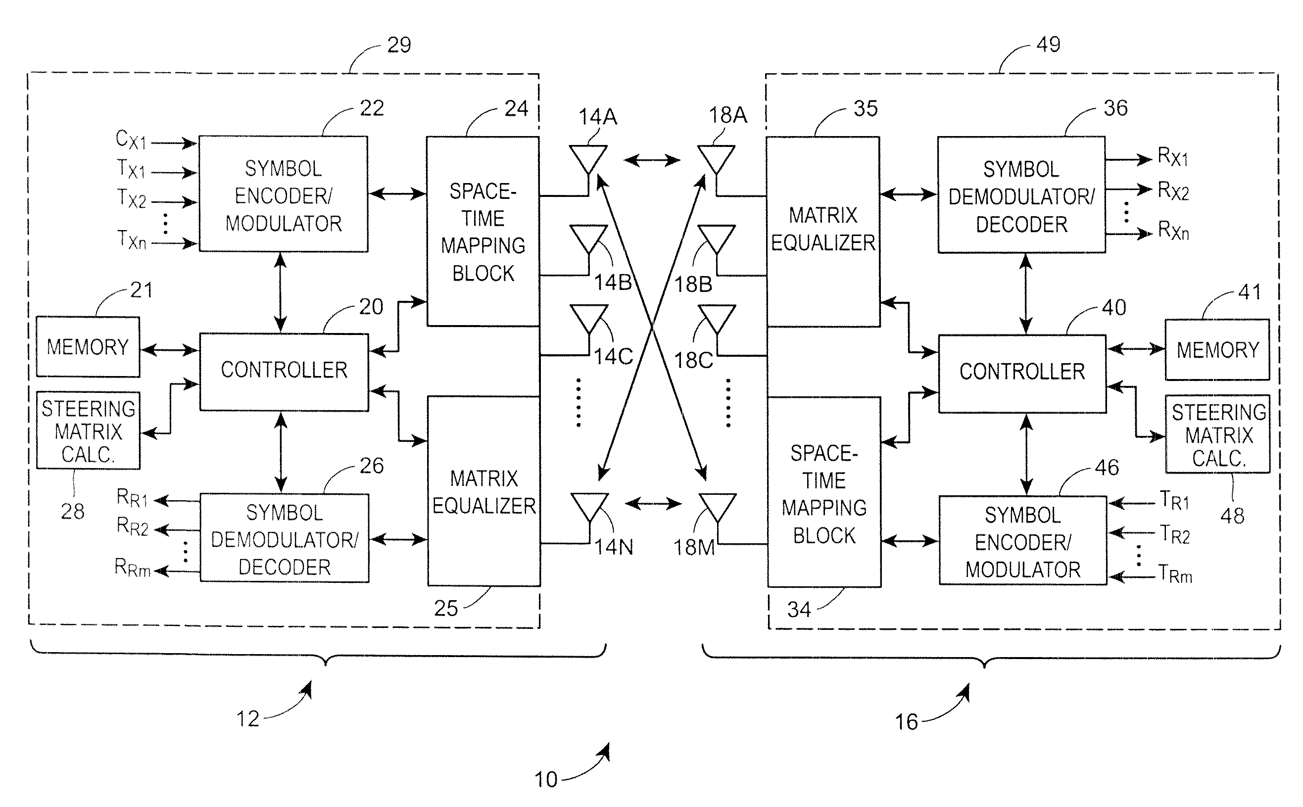
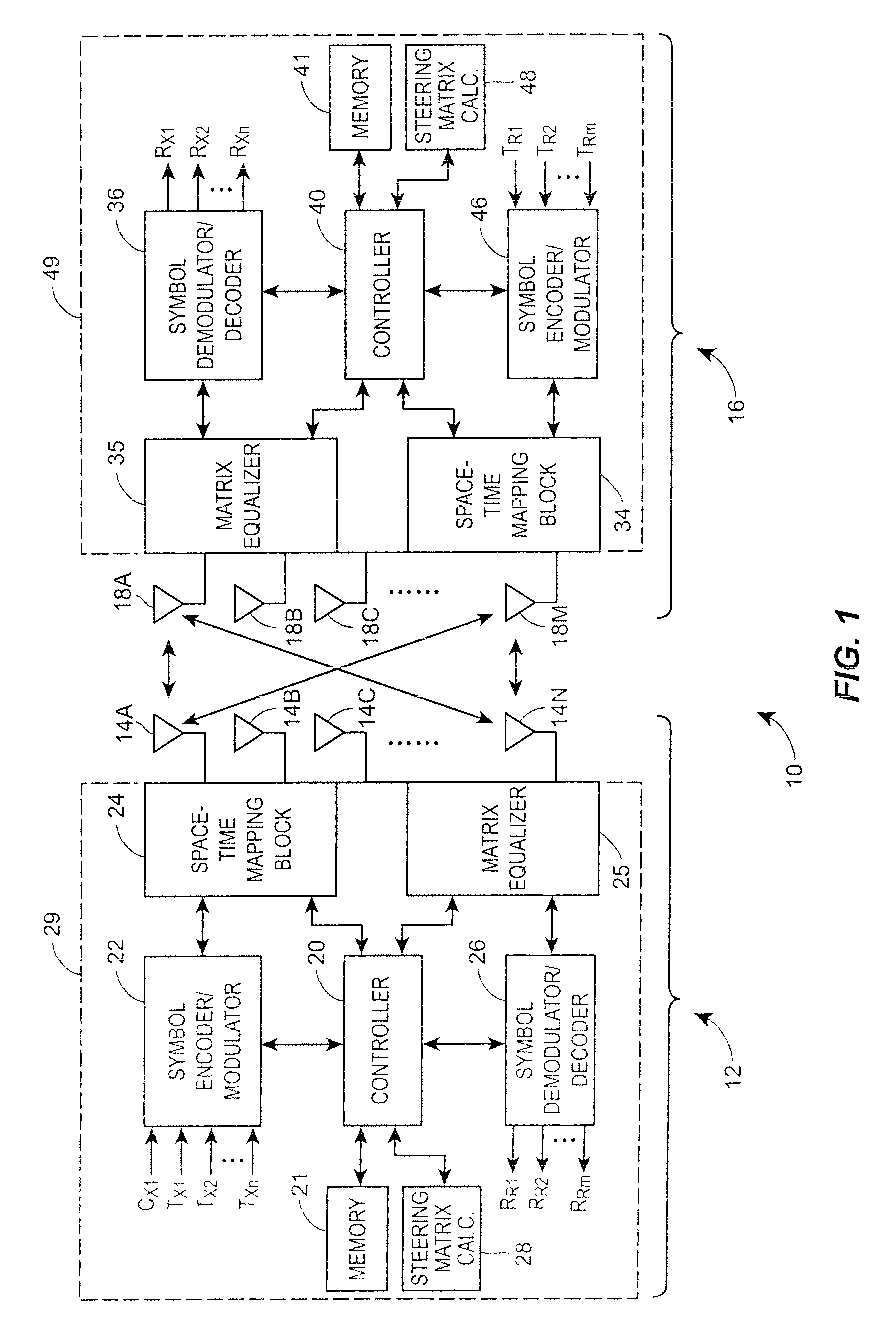
[0029]Referring now to FIG. 1, a MIMO communication system 10 is illustrated in block diagram form as generally including a single transmitter 12 having multiple transmission antennas 14A-14N and a single receiver 16 having multiple receiver antennas 18A-18M. The number of transmission antennas 14A-14N can be the same as, more than, or less than the number of receiver antennas 18A-18M. As shown in FIG. 1, the transmitter 12 may include a controller 20 coupled to a memory 21, a symbol encoder and modulator unit 22 and a space-time filtering or mapping block 24, also referred to...


PUM


Abstract

A beamforming technique used in a MIMO wireless transmission system performs beamforming based on a subset of the receiver antennas within the communication system to increase the speed and / or to decrease the processing needed to implement effective beamforming at the transmitter of the MIMO system. This beamforming technique can provide increased performance over no beamforming without significantly increasing the processing overhead of the transmission system, especially when a large number of receiver antennas are present at a receiver of the MIMO system. This beamforming technique can additionally be used when a transmitter, with multiple transmission antennas, is used to communicate with multiple receivers, each of which includes one or more receiver antennas. In this case, the beamforming technique may select a subset of the receiver antennas that includes, for example, one receiver antenna from each of the receivers, and may then beamform to the selected subset of receiver antennas.

Description

RELATED APPLICATION[0001]This is a regular-flied application which is based on and claims priority to U.S. Provisional Patent Application Ser. No. 60 / 796,848, entitled “Beamforming to a Subset of Receive Antennas in MIMO Systems,” which was filed on May 2, 2006, the entire disclosure of which is hereby incorporated by reference herein.FIELD OF TECHNOLOGY[0002]The present invention relates generally to wireless communication systems and, more particularly, to a method and system for beamforming while transmitting information in a multiple-input, multiple-output wireless communication system.DESCRIPTION OF THE RELATED ART[0003]An ever-increasing number of relatively cheap, low power wireless data communication services, networks and devices have been made available over the past number of years, promising near wire speed transmission and reliability. Various wireless technology is described in detail in the 802.11 IEEE Standard, including for example, the IEEE Standard 802.11a (1999) ...

Claims


Application Information

Patent Timeline
Patent Type & Authority Patents(United States)
IPC IPC(8): H04B7/02H04B1/40
CPCH04B7/0874H04B7/043H04B7/0408H04B7/0417H04B7/0473H04B7/061
Inventor NABAR, ROHITLOU, HUI-LING
Owner NXP USA INC
Why Eureka
Try Eureka