Multifocal lens array and three-dimensional stereoscopic image display apparatus

a stereoscopic image and display apparatus technology, applied in the field of multi-focal lens arrays and three-dimensional stereoscopic image display apparatuses, can solve the problems of high cost, inability to view stereoscopic images, and inability to see stereoscopic images, so as to achieve simple structure, low cost, and small size

Inactive Publication Date: 2010-09-07
FUJI ELECTRIC CO LTD
View PDF14 Cites 4 Cited by
  • Summary
  • Abstract
  • Description
  • Claims
  • Application Information

AI Technical Summary

Benefits of technology

[0010]According to the above constitution, light from the display screen of the display apparatus which displays a two-dimensional image is reflected by reflecting surfaces of the reflecting object in the optical path of the light, and the reflecting object is moved. The display apparatus successively displays separate images (sections of the stereoscopic image) in response to the movement. A viewing person remembers an after-image, and hence upon moving the reflecting object rapidly, it looks just as if the stereoscopic image is in space. Moreover, the apparatus can be realized with a simple structure and can be made small in size so that the installation site is not subject to many restrictions and the cost can be kept down.
[0021]According to the present invention, a multifocal lens array and a three-dimensional stereoscopic image display apparatus are provided which can be realized with a simple structure, which can be made small in size, for which the installation site is not subject to many restrictions, and for which the cost can be kept down.

Problems solved by technology

However, for methods in which the difference in viewing angle between the left and right eyes is used, as in, for example, Japanese Patent Application Laid-open No. 2000-115812, U.S. Pat. Nos. 6,525,699, 6,940,473, 6,950,078, and 7,002,532, there exists the problem that, while a stereoscopic image can be seen when viewed from a certain direction, when viewed from another place either viewing is not possible or a stereoscopic image cannot seen.
Moreover, in the case of using lasers or the like, there is a problem that the apparatus is large and hence there are limitations on the installation site due to restrictions relating to size, weight and so on, and, moreover, the cost is high.

Method used


Image

  • Multifocal lens array and three-dimensional stereoscopic image display apparatus
  • Multifocal lens array and three-dimensional stereoscopic image display apparatus
  • Multifocal lens array and three-dimensional stereoscopic image display apparatus

Examples


first embodiment

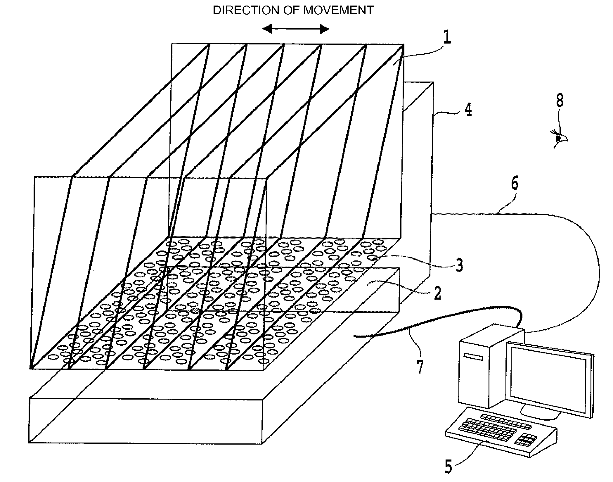
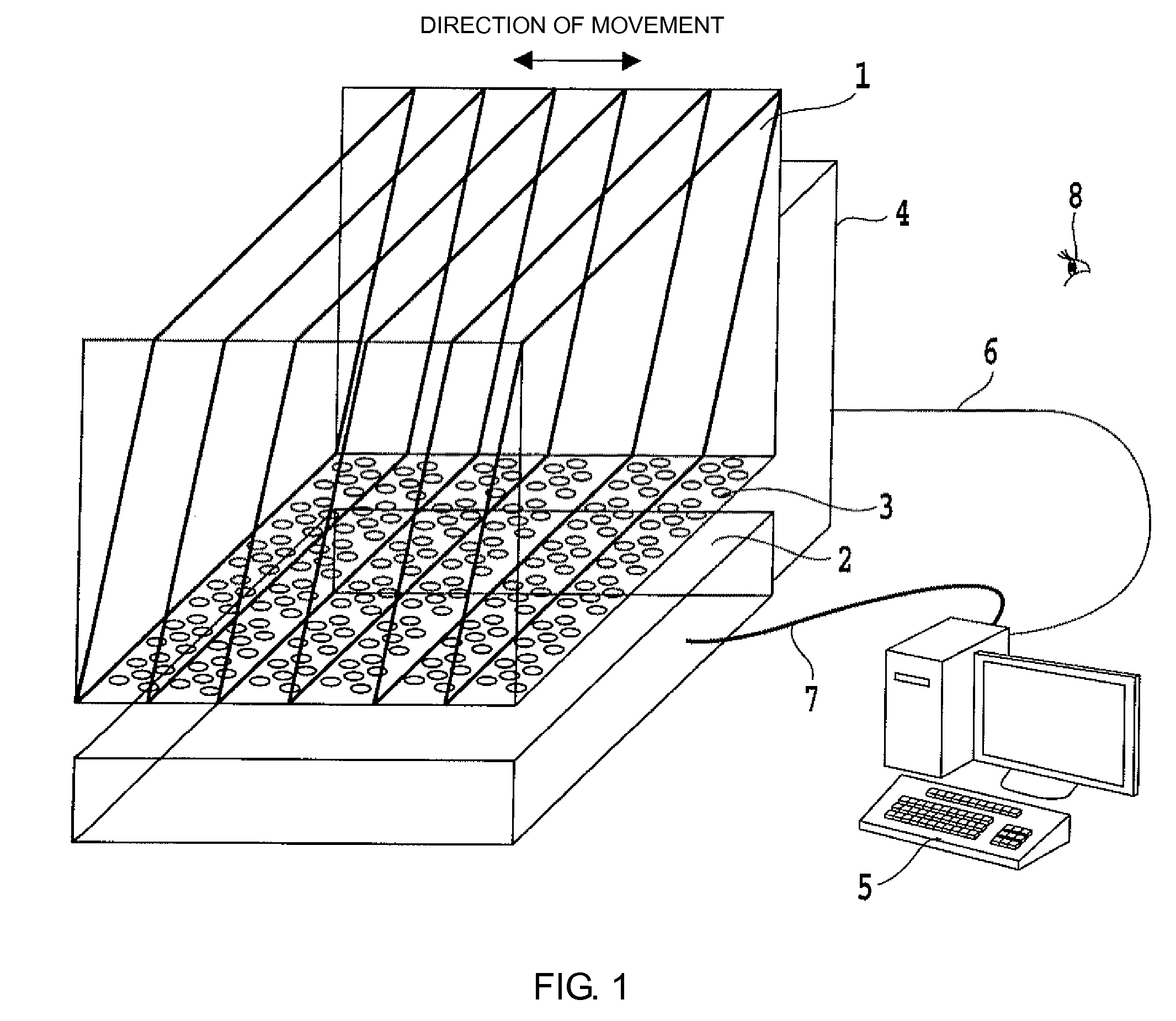
[0043]FIG. 1 shows the whole of a three-dimensional stereoscopic image display apparatus according to a first embodiment. Reference numeral 2 designates a flat display apparatus which is a display apparatus on which a two-dimensional image is displayed. The flat display apparatus 2 displays a two-dimensional image on a display screen in response to two-dimensional image data supplied from a computer system 5 via an output cable 7. Reference numeral 1 designates a stereoscopic diffusing panel which is a reflecting object having six films each comprising a planar surface arranged parallel to one another at equal intervals. The stereoscopic diffusing panel 1 is supported directly above the display screen of the flat display apparatus 2, i.e., in an optical path of image light from the display screen, by a driving apparatus 4, whose operation will be described later, such that each of the films is positioned obliquely relative to the display screen.

[0044]Each of the films of the stereos...

second embodiment

[0054]FIG. 9 shows the whole of a second embodiment. As shown in FIG. 9, in the present embodiment, the structure of the stereoscopic diffusing panel is different from that of the first embodiment, the method of driving the stereoscopic diffusing panel is also different from that of the first embodiment and, furthermore, the image data supplied to the flat display apparatus 2 is different from that in the first embodiment.

[0055]For the driving apparatus 4, a rotating shaft 9 is disposed via a suitable arm (not shown) perpendicular to the display screen of the flat display apparatus 2 directly above the flat display apparatus 2. Four panels (curved plates) 1a, 1b, 1c, and 1d constituting the stereoscopic diffusing panel are fixed to the rotating shaft 9, and are rotated about the rotating shaft 9. The four panels 1a, 1b, 1c, and 1d are fixed to the rotating shaft 9 every 90°. For each of the four panels 1a, 1b, 1c, and 1d, each of a lower edge and an upper edge is a straight line, an...

third embodiment

[0064]In the present embodiment, the whole of which is shown in FIG. 14, the constitution is as in the second embodiment except that a liquid crystal projector 10 is used as the display apparatus. The liquid crystal projector 10 uses an optical system for enlarged display and, hence, a mirror 11 is provided which converts projected light from the liquid crystal projector 10 into parallel light and projects the parallel light onto the stereoscopic diffusing panel 1 via the lens array 30. Other than this optical system, the processing can be carried out as in the second embodiment. Note that the liquid crystal projector 10 and the mirror 11 can be designed so as to have a constitution specially for the present invention thus avoiding waste.


PUM


Abstract

A multifocal lens array and a three-dimensional stereoscopic image display apparatus, which has a low cost, simple structure. A two-dimensional image is displayed on a display apparatus and is incident on a multifocal lens array. The array includes a plurality of lenses arranged on a planar surface, respective focal distances of the lenses being selected so that a focal point-containing surface is formed at a surface inclined relative to the planar surface. A stereoscopic diffusing panel including six transparent panels is disposed at the focal point-containing surface, and is moved periodically in a depth direction, so that sectional images of a three-dimensional stereoscopic image are rendered on the stereoscopic diffusing panel through image light from the apparatus, and hence a person viewing light reflected from the stereoscopic diffusing panel can see the three-dimensional stereoscopic image due to an after-image effect.

Description

BACKGROUND OF THE INVENTION[0001]1. Field of the Invention[0002]The present invention relates to a multifocal lens array and to a three-dimensional stereoscopic image display apparatus that displays a three-dimensional stereoscopic image in three-dimensional space.[0003]2. Description of the Related Art[0004]It is anticipated that display of stereoscopic images will be widely used in fields such as the following so long as the display performance and cost are appropriate. In the medical field, by displaying stereoscopic data from a CT scan or the like in space, a diseased site can be identified before surgery, which is very useful. In construction, by viewing CAD data stereoscopically, spatial checking of areas can be carried out, which again is useful. In facility design, robot design and so on, the spatial arrangement of components can actually be seen, and hence design can be carried out with no waste. Moreover, in town planning and regional development, by carrying out studies u...

Claims


Application Information

Patent Timeline
Patent Type & Authority Patents(United States)
IPC IPC(8): G02B27/10G03B21/60G02B3/00G02B27/22G03B35/00G03B35/18H04N13/395
CPCG02B3/0043G02B3/0056G02B27/2285H04N13/0495H04N13/395G02B30/54
Inventor YOKOSAWA, TERUHISA
Owner FUJI ELECTRIC CO LTD
Why Eureka
Try Eureka