Wireless sensor device

a sensor device and wireless technology, applied in the direction of process and machine control, wireless architecture, instruments, etc., to achieve the effect of prolonging the operating life of the power supply, saving energy, and less power consumption

Inactive Publication Date: 2010-09-07
MATSUSHITA ELECTRIC WORKS LTD
View PDF13 Cites 30 Cited by
  • Summary
  • Abstract
  • Description
  • Claims
  • Application Information

AI Technical Summary

Benefits of technology

[0005]In view of the above problem, the present invention has been accomplished to provide a wireless sensor device which is less power consuming and is capable of operating over a prolonged period of time for providing a reliable sensor result. The wireless sensor device includes a sensor configured to sense a target object and provide a sensor signal of varying levels indicative of condition of the target object, a signal processing circuit configured to amplify the sensor signal and provide an amplified electric analog signal, and a detection circuit configured to receive the amplified analog signal and provide a detection output (Dout) when the electric analog signal goes beyond a predetermined detection threshold. Also included in the device is a radio transmitter which is configured to transmit a radio detection signal (RS) in response to the detection output. Further, the device includes a power supply configured to provide an electric power to the signal processing circuit and the radio transmitter; and a power generating element which converts an external energy into the electric power to be accumulated in the power supply. A controller is included to activate the radio transmitter only in response to the detection output, permitting the radio transmitter to generate the radio detection signal. Accordingly, the radio transmitter can be kept inactivated until receiving the detection output, thereby saving energy to prolong the operating life of the power supply and, i.e., the device.
[0006]In a preferred embodiment, the radio transmitter includes a regulator, a clock, a pulse generator, and a driver. The regulator is connected to receive the electric power from the power supply and is configured to supply an operating voltage for a short time period only upon receiving the detection output from the detection circuit. The clock is activated upon receiving the operating voltage from the regulator to provide a clock signal. The pulse generator is configured to generate, based upon the clock signal, short pulses identifying the presence of the detection output. The driver is activated upon receiving the operating voltage from the regulator to radiate the short pulses as the radio detection signal through an antenna. With this arrangement, the clock and the driver are made active only upon receiving the detection output for transmitting the radio detection signal. Accordingly, the driver, which is inherently the most power consuming unit in the radio transmitter, can be kept deactivated in the absence of the detection output, whereby the radio transmitter is held in a minimum power consumption mode while not receiving the detection output, which enables to further reduce a power requirement to the device and therefore prolong the effective operating time.
[0008]The sensor may be an infrared ray sensor for detection of a motion of the target object by monitoring a critical change of infrared ray emitted from the target object, for example, human body. The infrared ray sensor is configured to provide the sensor signal which varies in positive or negative directions in response to the motion of the target. In this instance, the detection circuit is configured to have a threshold selector which provides a detection range (A1-A2) defined by upper positive and lower negative ones of said detection threshold, and also a wake-up range (B1-B2) defined by upper positive and lower negative ones of the wake-up threshold. The detection circuit includes a comparator unit which receives the detection range and the wake-up range selectively from the threshold generator for comparison of the analog signal with the selected one of the ranges. The comparator unit generates a first signal either when the electric signal (Vout) of rated amplitude goes beyond the detection range or when the electric signal (Vout) of low amplitude goes beyond said wake-up range, and otherwise generating a second signal. The controller is configured to select the detection range in response to the first signal, and select the wake-up range in response to the second signal. The detection circuit provides the detection output only upon seeing the first signal in the normal mode. Accordingly, the sensor device can successfully detect the motion of the target object using the infrared ray sensor, while saving energy.
[0009]The detection circuit may include an output provider which is configured to generate the detection output (Dout) when receiving the first signal from the comparator unit at an input of said output provider. The input is connected to the comparator unit through a switch which is controlled by the controller to close only in response to the first signal. Thus, the output provider is protected from generating a false detection signal in the absence of the first signal, thereby improving detection reliability.
[0010]Further, the controller is connected to monitor a level of the electric power accumulated in the power supply for keeping the normal mode and disabling the sleep move while the electric power is higher than a predetermined power level. That is, while sufficient power is available, the detection circuit is kept free from a shifting between the modes, and therefore can be free from being influenced by unstable circuit operation which might appear during the transient mode shifting, assuring a reliable detection.

Problems solved by technology

Because of that the solar cell is not expected to constantly generate sufficient power to keep the system operative, the system requires a power regulator which enables operation only while much power is being generated at the solar cell in order to transmit a reliable sensor result.

Method used


Image

  • Wireless sensor device
  • Wireless sensor device
  • Wireless sensor device

Examples


Embodiment Construction

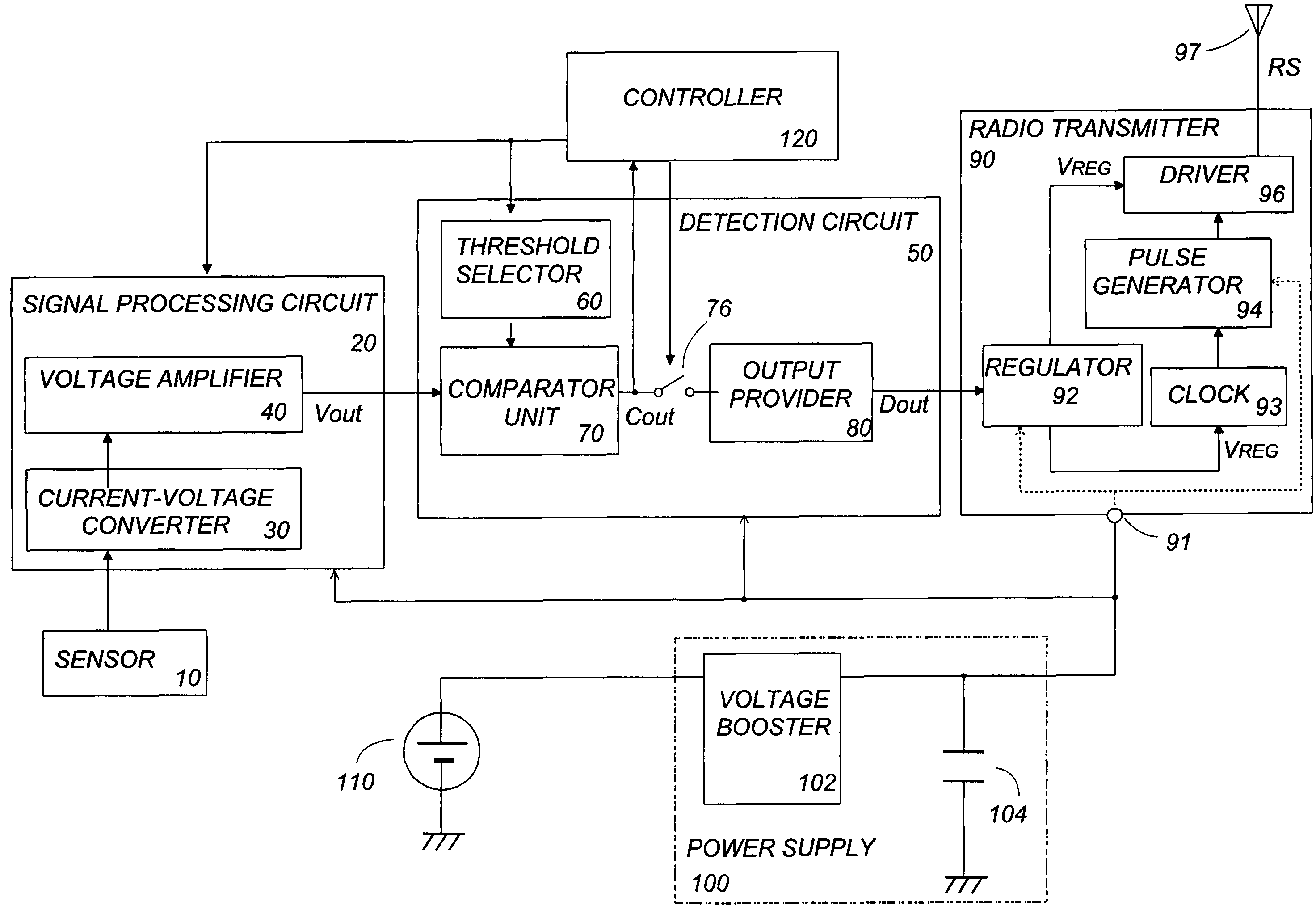
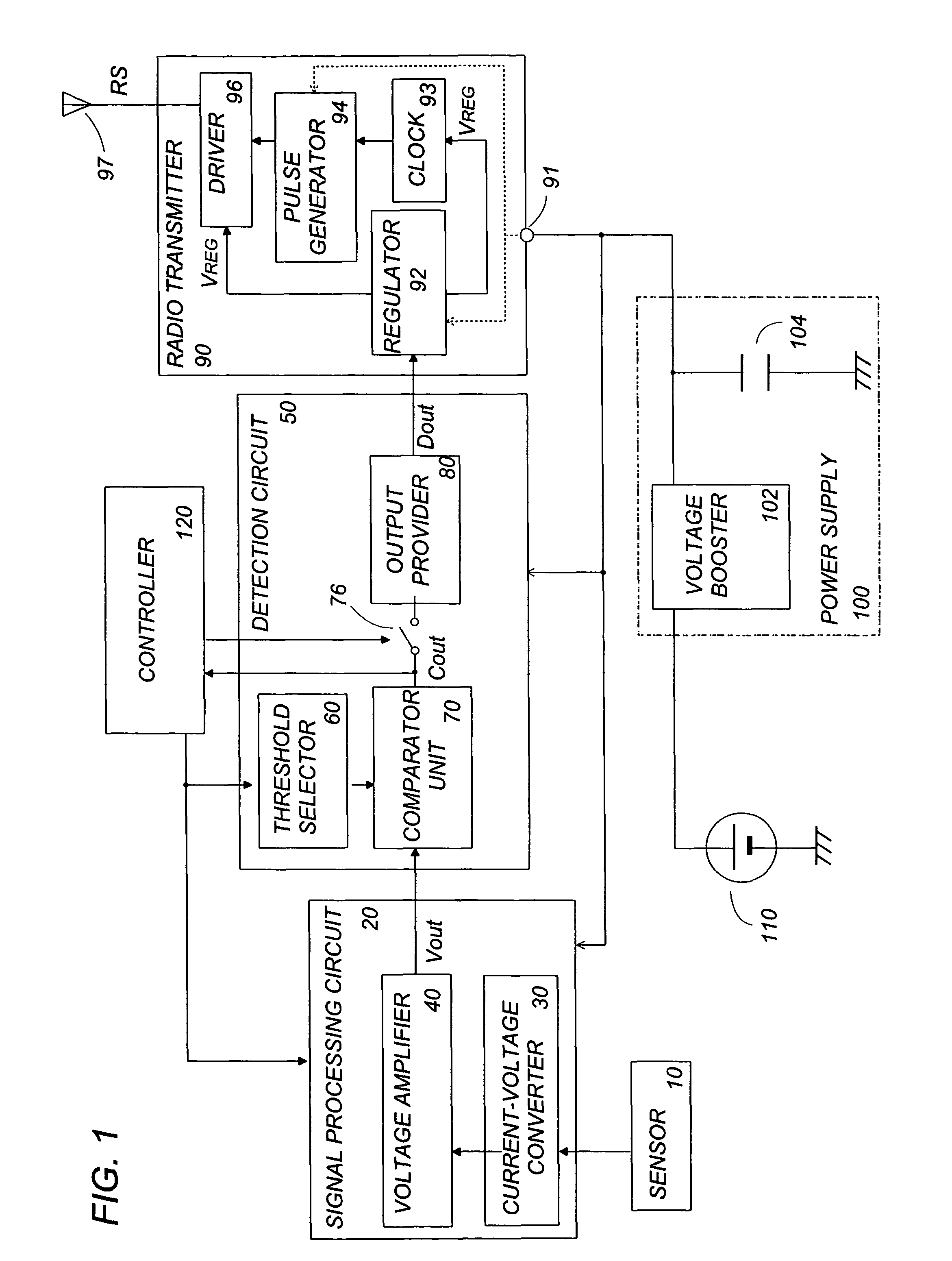
[0018]Referring now to FIG. 1, there is shown a sensor device in accordance with an exemplary embodiment of the present invention. The device is specifically arranged to detect human motion, i.e. whether the human comes into or out of a surveillance area by use of an infrared ray sensor which generates an electric sensor signal responsive to infrared radiation from the human, although the present invention should not be limited to this particular instance. The infrared ray sensor 10 generates the sensor signal which varies in positive and negative directions in response to the motion of the human coming into and out of the surveillance area.

[0019]The device includes a signal processing circuit 20 which processes the sensor signal to provide an amplified analog signal, and a detection circuit 50 which compares the analog signal with predetermined criteria to provide a detection output according to the comparison result. The device further includes a radio transmitter 90 which, in res...


PUM


Abstract

A wireless sensor device including a sensor configured to sense a target object and provide a sensor signal of varying levels indicative of condition of the target object, a signal processing circuit configured to amplify the sensor signal and provide an amplified electric analog signal, and a detection circuit configured to receive the amplified analog signal and provide a detection output when the electric analog signal goes beyond a predetermined detection threshold. A radio transmitter transmits a radio detection signal in response to the detection output. A power supply is configured to provide an electric power to the signal processing circuit and the radio transmitter and includes a power generating element which converts an external energy into the electric power to be accumulated in the power supply. A controller activates the radio transmitter only in response to the detection output, permitting the radio transmitter to generate the radio detection signal.

Description

BACKGROUND OF THE INVENTION[0001]1. Field of the Invention[0002]The present invention is directed to a wireless sensor device, and more particularly to such a wireless device including a power generating element that converts an external energy into an electric power for transmitting a sensed result as a radio signal.[0003]2. Description of the Related Art[0004]Japanese Patent Publication No. 2004-24551 discloses a self-contained sensing system including a power generating means for transmitting a sensed result. The system includes a sensor for sensing a temperature, an acceleration, or infrared ray to provide a sensor signal indicative of a sensed analog value, and an A / D converter which converts the sensor signal into digital data. The digital data are processed by a microprocessor so as to be transmitted through a radio transmitter as a radio signal. A solar cell is included as the power generating means in order to supply an operating power to the A / D converter, the microprocess...

Claims


Application Information

Patent Timeline
Patent Type & Authority Patents(United States)
IPC IPC(8): H04B1/38
CPCH04Q9/00H04Q2209/40H04Q2209/886H04Q2209/883H04Q2209/823H05B47/13Y02B20/40G08B13/194G08C17/00G08C17/02
Inventor FUKUI, SUGURUHATATANI, TERUKITAKADA, YUJI
Owner MATSUSHITA ELECTRIC WORKS LTD
Why Eureka
Try Eureka