Fluid dynamic bearing system

a dynamic bearing and bearing technology, applied in the direction of sliding contact bearings, rigid support of bearings, manufacturing tools, etc., can solve the problems of reducing the useful life of bearings, affecting the bearing life, so as to reduce the thickness

Inactive Publication Date: 2010-09-14
MINEBEA CO LTD
View PDF13 Cites 9 Cited by
  • Summary
  • Abstract
  • Description
  • Claims
  • Application Information

AI Technical Summary

Benefits of technology

[0009]According to the invention, a bearing system is provided in which the counter plate has a reduced thickness at its outer edge and is welded in the region of this reduced thickness to the bearing sleeve. The reduced thickness of the counter plate at the region of its outer edge means that the vertical gap between the bearing sleeve and the counter plate is made very much shorter, or is done away with altogether, so that no unwanted air can remain in the gap.
[0011]According to a second embodiment of the invention, an overlapping welding process is employed which is used in pulsed operation since higher outputs are required for this. Here, the two workpieces, namely the bearing sleeve and the counter plate, are not welded together at their edges as is normally the case, but rather the welding process proceeds right through the outer material of the counter plate, the counter plate being welded in the region of its reduced thickness to the end face of the bearing sleeve. To this effect, the counter plate is made thinner, particularly at the contact surface to the bearing sleeve. This embodiment of the invention has the advantage that both the volume of air in the groove as well as the volume of air in the gaps are separated from the bearing interior and no longer play a part. The use of overlapping welding makes it preferable if the thickness of the outer edge of the counter plate is less than 0.5 mm. However, a thickness of 0.2 to 0.3 mm for the counter plate is preferential.

Problems solved by technology

This can then lead to a lower oil level within the bearing and contamination in the region outside the bearing.
This can result in a decrease in the useful life of the bearing or, in the worst case, to damage to the components outside the bearing.

Method used


Image

  • Fluid dynamic bearing system
  • Fluid dynamic bearing system

Examples


first embodiment

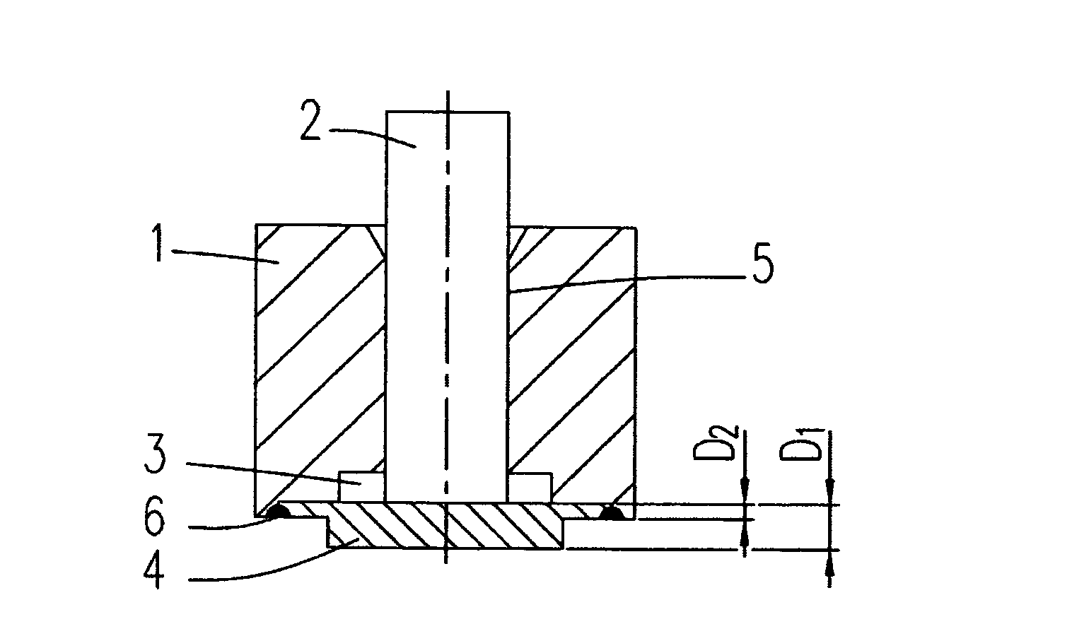
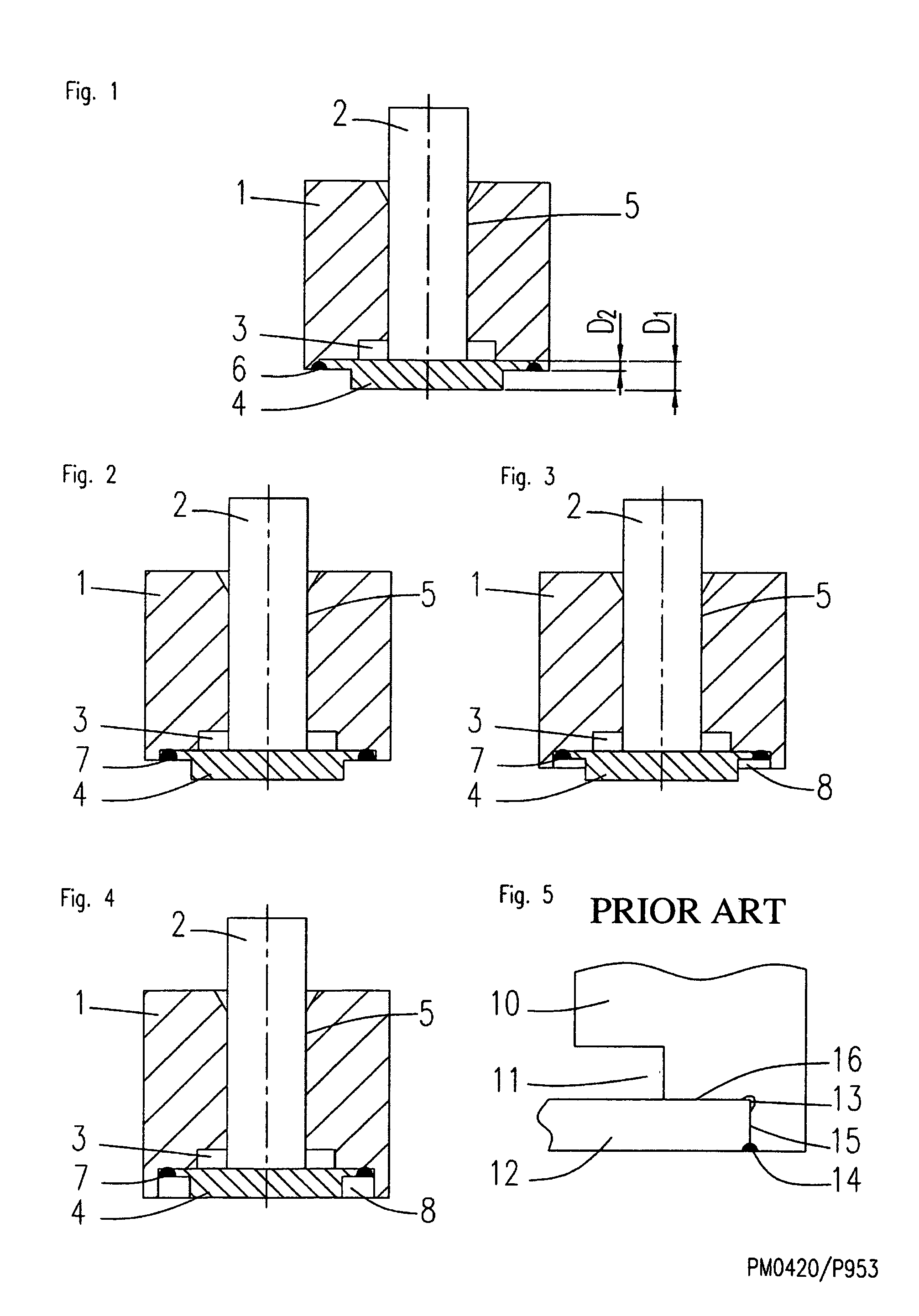
[0021]In the invention according to FIG. 1, the welded joint 6 is provided at the edges abutting each other of the bearing sleeve 1 and the counter plate 4, as is basically known. The workpieces to be welded 1 and 4 and the laser beam are moved with respect to each other during the welding process, preferably at a relative speed of 300 mm / s or more. The welding process is carried out with one single laser pulse per weld seam, the pulse duration being, for example, greater than or equal to 10 ms. Since the counter plate has a reduced thickness D2 at its outer edge and the recess in the bearing sleeve also has a reduced height, the length of the vertical gap 15 (FIG. 5) is reduced or even disappears entirely. This means that no unwanted air can collect in the gap 15.

second embodiment

[0022]In the invention according to FIGS. 2 to 4, the counter plate 4 is connected to the bearing sleeve 1 by an overlapping welding process. Here, the welding process proceeds right through the outer material of the counter plate 4, the counter plate 4 being welded in the region of its reduced thickness D2 to the end face of the bearing sleeve 1. The welded joint 7 extends at a certain distance to the thrust plate (recess 3).

[0023]In FIG. 2, the outer region of the counter plate ends in the same thickness D2 as the related region of the recess in the bearing sleeve 1, whereas in FIGS. 3 and 4 the thickness (height) of the recess 8 is greater than the thickness of the counter plate 4, so that a free space remains in which the overlapping welding process can take place. In FIG. 4, the outer end region of the bearing sleeve 1 lies on the same plane as the lower middle region of the counter plate 4, located below the shaft 2 and the recess 3 for the thrust plate.

[0024]Compared to the r...


PUM

PropertyMeasurementUnit
thicknessaaaaaaaaaa
poweraaaaaaaaaa
feed speedaaaaaaaaaa

Abstract

The invention relates to a fluid dynamic bearing system particularly for the purpose of rotatably supporting a spindle motor, having a first bearing part that comprises a bearing sleeve, and a second bearing part that comprises a shaft, the two bearing parts being spaced apart from one another by a bearing gap and being rotatable with respect to each other, wherein the bearing sleeve is closed at one end by a counter plate that is accommodated in an annular recess in the bearing sleeve and connected to the bearing sleeve by a welded joint. According to the invention, a bearing system is provided in which the counter plate has a reduced thickness (D2) at its outer edge and is welded in the region of its reduced thickness (D2) to the bearing sleeve. The reduced thickness of the counter plate at the region of its outer edge means that the vertical gap between the bearing sleeve and the counter plate is made very much shorter, or is done away with altogether, so that no unwanted air can remain in the gap.

Description

BACKGROUND OF THE INVENTION[0001]The invention relates to a fluid dynamic bearing system as used, for example, to rotatably support a spindle motor used to drive hard disk drives. The invention relates in particular to the construction of a joint between the bearing sleeve and counter plate of this kind of bearing system. A method of manufacturing such a bearing system is also described.PRIOR ART[0002]Spindle motors consist substantially of a stator, a rotor and at least one bearing system disposed between these two parts. Fluid dynamic sliding bearings are being increasingly employed as bearing systems. A fluid dynamic bearing system comprises a bearing sleeve and a shaft that is disposed in an axial bore in the bearing sleeve. The shaft rotates freely within the bearing sleeve, with the two parts together forming a radial bearing. The mutually interacting surfaces of the shaft and the bearing sleeve are spaced apart from one another by a thin, concentric bearing gap filled with a ...

Claims


Application Information

Patent Timeline
Patent Type & Authority Patents(United States)
IPC IPC(8): F16C32/06B23K26/00B23P15/26
CPCF16C17/04F16C35/02Y10T29/49636Y10T29/49668F16C2370/12F16C2226/36F16C43/02F16C17/045F16C17/107F16C33/103
Inventor NEUMANN, RUDOLF
Owner MINEBEA CO LTD
Why Eureka
Try Eureka