Surface finishing apparatus and related method

a surface finishing and surface technology, applied in the direction of wrenches, grinding machine components, manufacturing tools, etc., can solve the problems of troublesome achievement, inability to control the lapping operation so as to obtain the desired geometrical profile, and high cost of roller burnishing tools per se, so as to improve surface roughness, improve surface finish, and improve surface roughness

Inactive Publication Date: 2010-09-14
NISSAN MOTOR CO LTD
View PDF15 Cites 12 Cited by
  • Summary
  • Abstract
  • Description
  • Claims
  • Application Information

AI Technical Summary

Benefits of technology

[0014]Additionally, when in roller burnishing, since the burnishing roller is held in pressured contact with a whole axial surface of the crankshaft to improve the surface roughness, the whole axially extending surface of the crankshaft is entirely formed in too excellent surface finish. The presence of excessively small unevenness in the surface roughness of the pin portion of the crankshaft results in no formation of unevenness to form the oil sump in the sliding surface of the pin portion of the cran...

Problems solved by technology

However, the lapping apparatus of the related art is arranged to achieve lapping operation under a fixed lapping condition, involving a shoe pressure force to be applied during lapping operation, and in actual practice, the use of such mere fixed lapping condition results in an inability of controlling lapping operation so as to obtain a desire...

Method used


Image

  • Surface finishing apparatus and related method
  • Surface finishing apparatus and related method
  • Surface finishing apparatus and related method

Examples


first embodiment

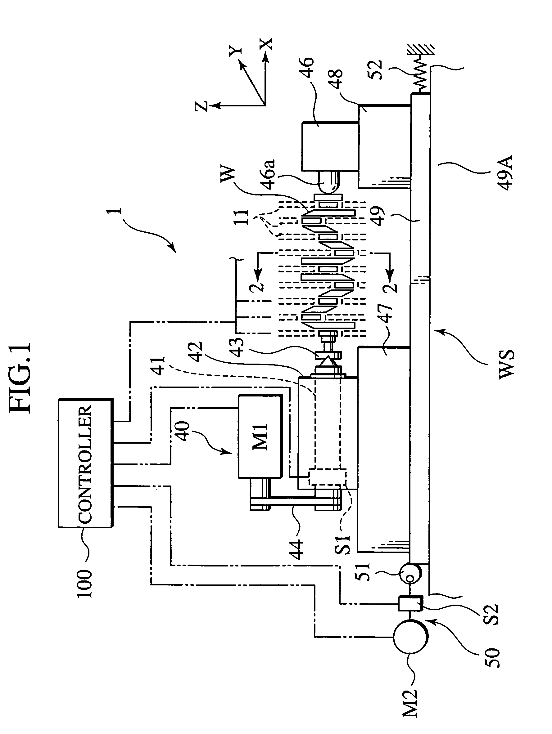
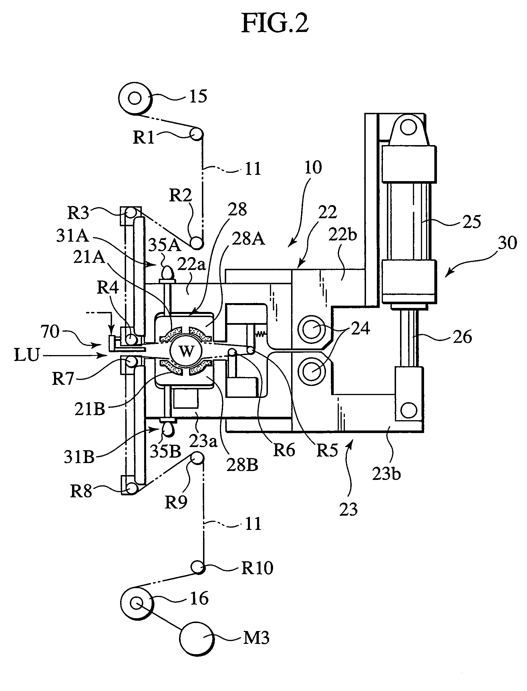
[0056]Referring now to FIGS. 1 and 2, there is shown a surface finishing apparatus, in the form of a lapping apparatus 1, of a first embodiment of the present invention. FIG. 1 is a schematic front view of the lapping apparatus, and FIG. 2 is a schematic view corresponding to a cross section taken on line 2-2 of FIG. 1.

[0057]As shown in FIGS. 1 and 2, the lapping apparatus 1 of the presently filed embodiment serves to finely lap a workpiece W, in the form of a crankshaft, in given surface finish subsequent to preceding rough surface machining operation, such as cutting using a machining tool, heat treatment and grinding operation. That is, the lapping apparatus 1 serves to lap a target shaped periphery of the workpiece W, such as a journal portion or a pin portion of the crankshaft, in a desired surface quality with a surface profile formed in a mid-concave shape. The lapping apparatus 1 is shown to include a workpiece supporting mechanism WS that supports the workpiece W having the...

second embodiment

Modified Form of Second Embodiment

[0152]FIG. 21 is a schematic view showing a modified form of the pressure applying mechanism 10A of the second embodiment shown in FIG. 13, with the same component parts as those of the second embodiment bear like reference numerals to omit redundant description.

[0153]The modified form shown in FIG. 21 differs from the second embodiment in structure in that eccentric rotary elements 135A and 135B, which are respectively replaced with the eccentric rotary elements 35A and 35B employed in the second embodiment and each of which is held correspondingly in abutting engagement with the head of the presser rod 34, respectively have an elliptical shape different from the cam shaped eccentric rotary elements 35A and 35B. Although as shown in FIG. 20, the use of the cam shaped eccentric rotary elements 35A and 35B provides the shoe pressure force P that varies in a relatively sharp fashion, the use of the eccentric rotary elements 135A and 135B respectively ...

third embodiment

[0160]FIG. 22 is a schematic view of a surface finishing apparatus of a third embodiment of the present invention, and FIG. 23 is a cross sectional view of the surface finishing apparatus shown in FIG. 22, with a pin portion of a workpiece being indicated in a slightly exaggerated form.

[0161]The surface finishing apparatus of the third embodiment differs from the first embodiment in that the surface finishing apparatus of the presently filed embodiment takes the form of a roller burnishing apparatus which allows roller burnishing process to be applied to the workpiece W, which is preliminarily lapped in a surface finish with a mid-concave profile in cross section as shown in FIG. 5 whereby a surface finish tool, in the form of a burnishing roller, is held in pressured contact with the workpiece W with a pressure force exhibiting a given distribution pattern depending upon an axial direction of the workpiece. Therefore, the same component parts as those of the first embodiment bear l...


PUM

PropertyMeasurementUnit
Fractionaaaaaaaaaa
Depthaaaaaaaaaa
Depthaaaaaaaaaa

Abstract

An apparatus and method for surface finishing a workpiece is disclosed as including a workpiece supporting mechanism supporting a workpiece having a target shaped periphery with a given width to be surface finished and a tool holder holding a surface finish tool in abutting contact with the target shaped periphery of the workpiece. A pressure applying mechanism is operative to apply a pressure force to the surface finish tool through the tool holder to cause the surface finish tool to be held in pressured contact with the target shaped periphery, with the pressure force exhibiting a given distribution pattern depending upon an axial direction of the workpiece. A drive mechanism rotates the workpiece to allow the surface finish tool to surface finish the target shaped periphery into a given geometrical profile, variably contoured along an axis of the workpiece depending on the given pressure distribution pattern.

Description

BACKGROUND OF THE INVENTION[0001]The present invention relates to a surface finishing apparatus and a related method and, more particularly, to a surface finishing apparatus and a related method for surface finishing a workpiece in a desired geometrical profile contoured along an axial direction of the workpiece.[0002]In the past, various attempts have been undertaken to lap a target shaped periphery, such as a journal portion or a pin portion, of a crankshaft of an automotive engine and subsequently to roller burnish the resulting surface in a desired surface roughness.[0003]The preceding lapping operation in such surface finishing is achieved by permitting the target shaped periphery of the workpiece to be covered with a lapping film and placing a plurality of shoes on a rear side of the lapping film whereupon, under a condition where the lapping film is held in pressured contact with the workpiece, the workpiece is rotated to allow an abrasive surface of the lapping film to lap t...

Claims


Application Information

Patent Timeline
IPC IPC(8): B24B7/30B24B5/42B24B19/12B24B21/00B24B49/16
CPCB24B5/42B24B19/12B24B21/00B24B49/16
Inventor KONDO, TOMOHIROIIZUMI, MASAHIKOOMATA, MASAHIROHASEGAWA, KIYOSHIOGINO, TAKASHIWATANABE, TAKAFUMICHIDA, YOSHIYUKIMATSUSHITA, YASUSHITAKEDA, KAZUO
Owner NISSAN MOTOR CO LTD
Why Eureka
Try Eureka