Battery module of high cooling efficiency

a battery module and high cooling efficiency technology, applied in battery/fuel cell control arrangement, cell components, maintenance/servicing of primary cells, etc., can solve the problems of large amount of heat generated by medium- or large-sized battery packs, degraded unit cells, and air pollution, and achieve high cooling efficiency and high cooling efficiency.

Active Publication Date: 2010-09-14
LG ENERGY SOLUTION LTD
View PDF74 Cites 14 Cited by
  • Summary
  • Abstract
  • Description
  • Claims
  • Application Information

AI Technical Summary

Benefits of technology

[0018]Specifically, it is an object of the present invention to provide a battery module using a coolant contact type cooling system in which the contact rate of a coolant to the surfaces of unit cells is increased, and the turbulent flow generating rate in coolant flow channels is increased, whereby the battery module has the high cooling efficiency under the same conditions.
[0020]In the contact type cooling system according to the present invention, as previously described, the coolant takes heat generated from the unit cells while the coolant flows through the flow channels defined between the unit cells. The coolant flow channels are decided based on in what shape the unit cells are spaced apart from each other. According to the present invention, the flow channels defined between the unit cells are at a predetermined angle to the flowing direction of the coolant at inlet ports of the flow channels. Consequently, after the coolant is introduced through the flow channel inlet ports, and the flow direction of the coolant is inclined while the coolant flows along the flow channels defined between the unit cells. At this time, turbulent flows occur, and therefore, the sectional velocity gradient is prevented. As a result, the contact rate of the coolant to the unit cells is increased, and therefore, the cooling efficiency of the battery module is improved.
[0025]The unit cells may be secondary batteries that can be charged and discharged. Typically, the unit cells may be nickel metal hydride secondary batteries, lithium-ion secondary batteries, or lithium-ion polymer secondary batteries. Among them, the lithium-ion secondary batteries are preferably used because the lithium-ion secondary batteries have high energy density and high discharge voltage. In terms of the shape of the unit cells, prismatic batteries or pouch-type batteries are preferably used. More preferably, the pouch-shaped batteries are used because the manufacturing costs of the pouch-shaped batteries are low, and the weight of the pouch-shaped batteries small.
[0031]In a preferred embodiment, the lower end frame of each cartridge is inclined at the same angle as the upper frame of each cartridge. Consequently, it is possible to more easily accomplish the stacking process of the cartridges.
[0033]The medium-or large-sized battery pack according to the present invention has high cooling efficiency. Consequently, the present invention is more preferably applied to a battery pack using lithium secondary batteries having a large amount of heat generation as unit cells. Although the size of the battery pack is small, the battery pack according to the present invention provides high cooling efficiency. Consequently, the battery pack is preferably used as a compact power source for electric vehicles, hybrid electric vehicles, or electric bicycles.

Problems solved by technology

One of the biggest problems caused from vehicles using fossil fuel, such as gasoline and diesel oil, is creation of air pollution.
However, a large amount of heat is generated from the medium- or large-sized battery pack during the charge and the discharge of the battery pack.
When the heat generated from the unit cells during the charge and the discharge of the battery pack is not effectively removed, heat is accumulated in the battery pack with the result that the unit cells are degraded.
According to circumstances, the unit cells may catch fire or explode.
However, this method is not preferable in that larger cooling fan or stronger fan driving unit is necessary.

Method used


Image

  • Battery module of high cooling efficiency
  • Battery module of high cooling efficiency
  • Battery module of high cooling efficiency

Examples


Embodiment Construction

[0044]Now, preferred embodiments of the present invention will be described in detail with reference to the accompanying drawings. It should be noted, however, that the scope of the present invention is not limited by the illustrated embodiments.

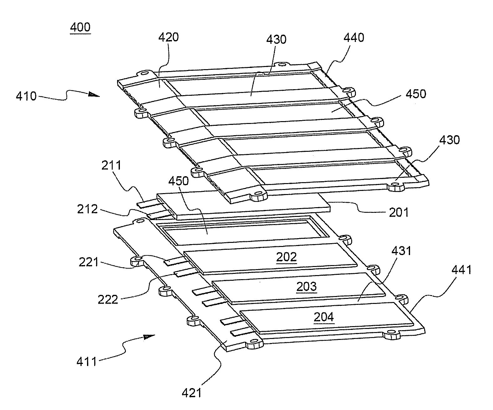
[0045]FIG. 5 is a typical view illustrating a process for mounting unit cells in a battery cartridge that can be used to construct a battery module according to a preferred embodiment of the present invention, and FIG. 6 is a perspective view typically illustrating the battery cartridge, in which the unit cells are mounted therein.

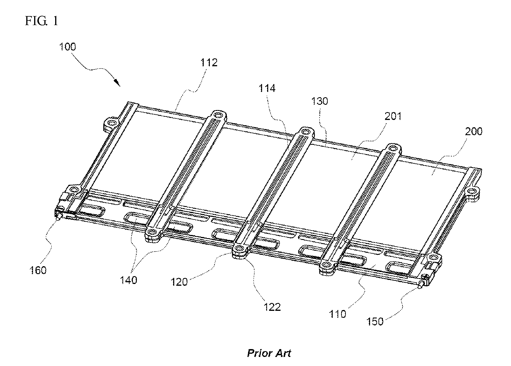
[0046]Referring to these drawings, a battery cartridge 400 is very similar or identical in the basic structure to the battery cartridge 100 of FIG. 1. Specifically, a plurality of plate-shaped unit cells 201, 202, 203, 204 are mounted between a pair of coupling type upper and lower frame members 410 and 411 such that the unit cells are arranged in lateral direction.

[0047]The unit cells 201, 202 . . . are pouch-shap...


PUM

PropertyMeasurementUnit
angleaaaaaaaaaa
angleaaaaaaaaaa
angleaaaaaaaaaa

Abstract

A battery module is provided. The battery module includes a plurality of unit cells stacked proximate to one another. The plurality of unit cells define flow channels therebetween. Each unit cell of the plurality of unit cells is longitudinally positioned at a predetermined angle in a range between 3 and 14 degrees relative to a wall of an input port for a respective flow channel. The battery module further includes a cooling system that routes a coolant through the flow channels between the plurality of unit cells such that the coolant contacts the plurality of unit cells.

Description

FIELD OF THE INVENTION[0001]The present invention relates to a battery module having high cooling efficiency, and, more particularly, to a battery module having a cooling system for cooling a plurality of unit cells by a coolant flowing between the unit cells, wherein flow channels, through which the coolant flows between the unit cells, are at a predetermined angle to an inlet ports of the flow channels, whereby the contact rate of the coolant to the surfaces of the unit cells is increased, the turbulent flow generating rate in the coolant flow channels is increased, and therefore, the battery module has high cooling efficiency under the same conditions.BACKGROUND OF THE INVENTION[0002]One of the biggest problems caused from vehicles using fossil fuel, such as gasoline and diesel oil, is creation of air pollution. A technology of using a secondary battery, which can be charged and discharged, as a power source for vehicles has attracted considerable attention as one method of solvi...

Claims


Application Information

Patent Timeline
Patent Type & Authority Patents(United States)
IPC IPC(8): H01M10/50H01M6/42H01M50/211H01M50/264
CPCB60L11/1874H01M2/1016H01M6/5038H01M10/5004H01M10/5067H01M10/5073H01M10/5016Y02T10/705Y02T10/7005Y02T10/7011H01M10/625H01M10/6563H01M10/6566H01M10/613B60L58/26Y02T10/70Y02E60/10H01M50/264H01M50/211H01M10/6569H01M10/6556
Inventor YANG, JAE HUN
Owner LG ENERGY SOLUTION LTD
Why Eureka
Try Eureka