Electric motor

a technology of electric motors and synchronous motors, applied in the direction of motor/generator/converter stoppers, dynamo-electric converter control, etc., can solve the problems of increasing maintenance requirements, complex slip-ring synchronous motors, and simple and cheap manufacturing of induction motors, so as to improve the efficiency of motors and effectively capture the magnetic flux density

Inactive Publication Date: 2010-09-14
ELCKON
View PDF3 Cites 37 Cited by
  • Summary
  • Abstract
  • Description
  • Claims
  • Application Information

AI Technical Summary

Benefits of technology

[0010]control means which is configured to regulate the magnetizing of the field winding by applying a voltage to the armature phase linked to the field winding via the lower reluctance path so that the energized armature phase in turn imposes a reverse voltage bias across the switch through induction, this reverse bias preventing the flow of current in the field winding but the applied voltage to the armature phase increasing magnetic flux density in the rotor, the control means thereafter removing said applied voltage once a predetermined flux density in the rotor is reached so that the removal of applied voltage induces a reversal of voltage to a forward voltage bias across the switch allowing current to flow in the field winding which current prevents the decay of the flux density in said rotor, and which control means is further configured to regulate the production of torque in the motor by applying a voltage to the other respective armature phase not responsible for energizing the field winding, so that, at any given moment, one armature phase is usable for magnetizing the field winding whilst the other phase is responsible for torque production.
[0011]It is to be appreciated that the selective switch in the field winding improves the efficiency of the motor by effectively capturing the magnetic flux density in the rotor when current is allowed to flow in the field winding. This no longer requires the armature winding to supply magnetizing current continuously as well as torque current, as is the case with, for example, existing induction motors.
[0013]The armature may include a plurality of packed slotted metal laminations to reduce eddy-currents in the armature. The rotor may include a plurality of packed slotted metal laminations to reduce eddy-currents in the rotor.
[0018]The control means may regulate the flux density in the rotor depending on the speed of the motor, e.g. at high speed the magnetization of the field winding need only be topped up every few revolutions of the rotor, whereas at low speed the field winding may require topping up multiple times during one revolution of the rotor.

Problems solved by technology

The induction motor is simple and cheap to manufacture but does not offer the performance of the synchronous motor.
On the other hand, slip-ring synchronous motors are more complex and expensive because of the exciter, slip rings and brushes required for operation.
This also increases maintenance requirements, whereas the induction motor is virtually maintenance free.
Brush DC motors have similar drawbacks although they are easier to control and have excellent traction characteristics.
The slip rings and brushes are eliminated in brushless synchronous motors but the AC brushless exciter configuration still means additional cost, space and complexity.
However, the manufacture and high cost of high field strength permanent magnets, and the process of attaching these magnets to the rotor, especially for large machines, becomes an engineering challenge.
The maximum field strength of permanent magnets is also limited by the current state of the art.
The synchronous induction motor, although very simple in construction, is not very efficient and is generally much larger than a slip-ring synchronous motor for similar performance.
In practice, synchronous induction motors have not found much use above a few kilowatts.

Method used


Image

  • Electric motor
  • Electric motor
  • Electric motor

Examples


Embodiment Construction

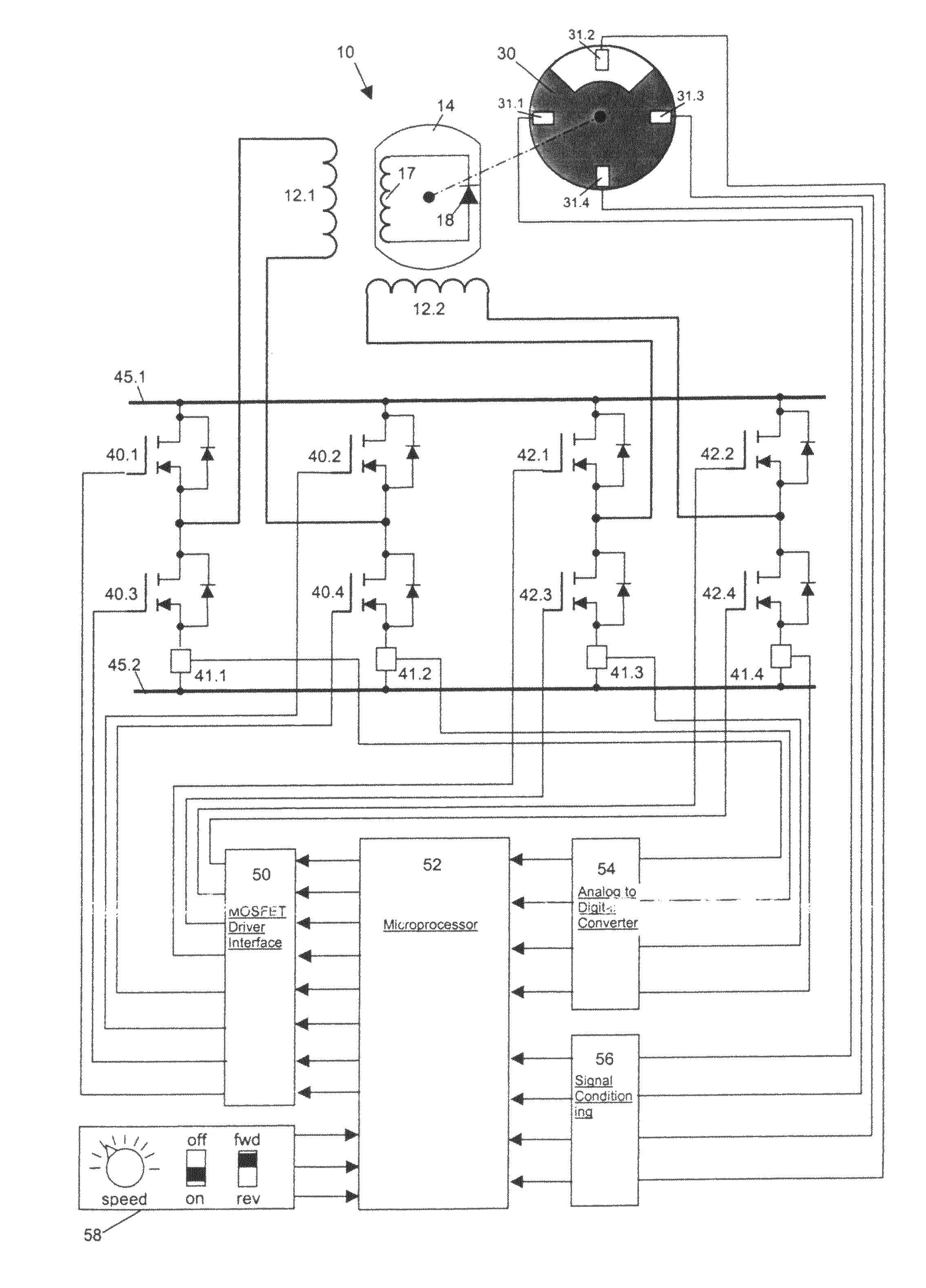
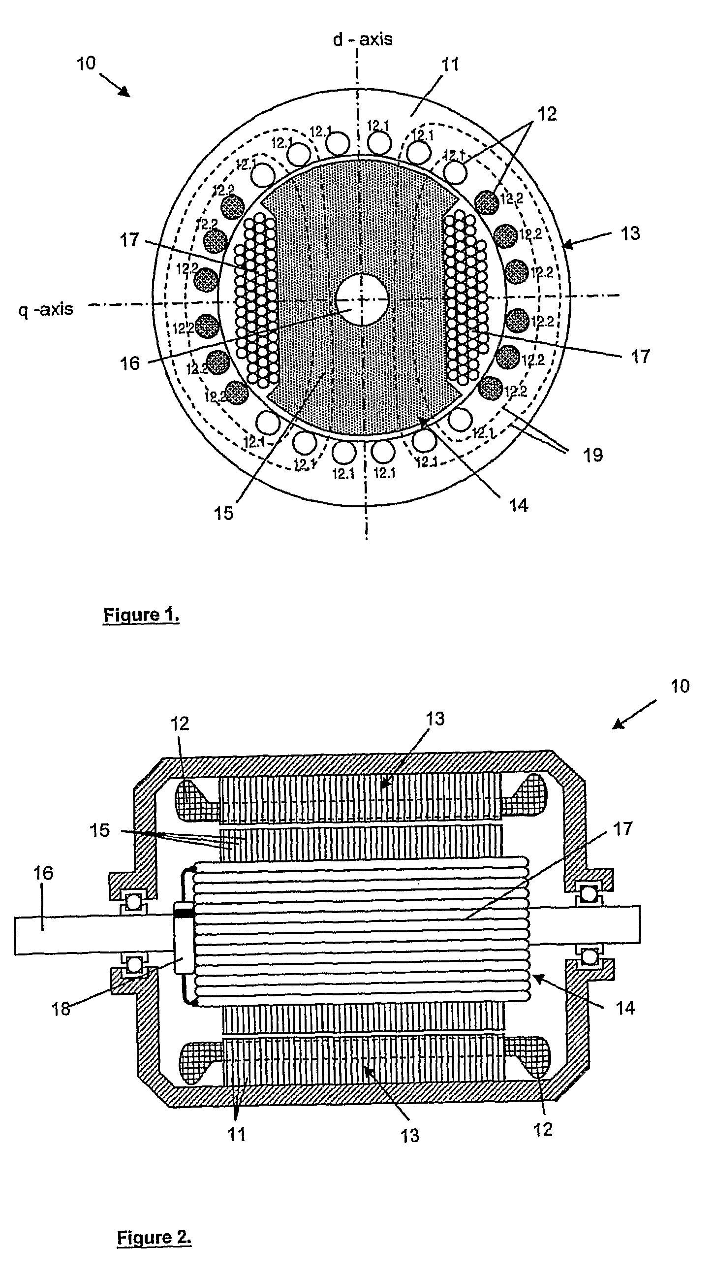
[0030]With reference to the accompanying drawings, an electric motor, in accordance with the invention, is generally indicated by reference numeral 10.

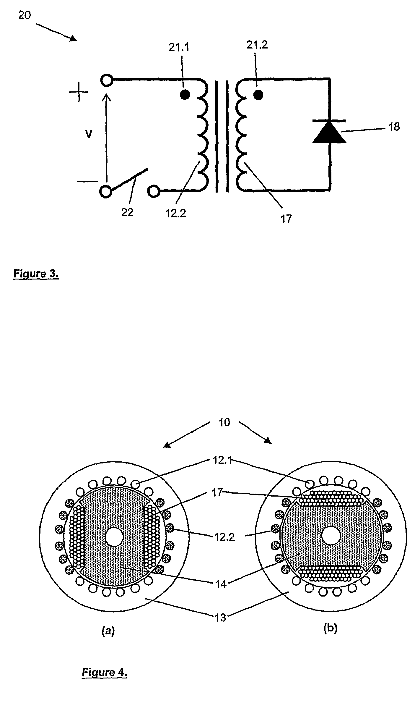
[0031]Referring to FIGS. 1 and 2, the outer member of the motor 10 consists of packed slotted steel laminations 11 for holding the armature windings 12, which together constitute the stator 13. The armature windings 12 are further divided into two separate windings 12.1 and 12.2 constituting two separate phases.

[0032]Similarly, the inner member consists of packed steel laminations 15 relatively fixed to a drive shaft 16 with a field winding 17 terminating in the selective switch being a freewheeling diode or rectifier 18 in this embodiment which collectively constitute the rotor 14 being able to rotate relative to the stator 13.

[0033]It is to be appreciated that, for the purposes of explanation, a reference coordinate system d-q is shown on FIG. 1. This coordinate system is rotatively associated or referenced to the rotor 14. Regardin...


PUM


Abstract

An electric motor (10) which includes an armature (11) with at least two armature phase pair windings (12) and salient pole rotor arrangement (15) having field windings (17) terminating in a selective electrical switch which determines the electrical continuity of said field windings (17). Also included is control means which is configured to regulate the magnetizing of the field winding (17) so that, at any given moment, one armature phase pair is usable for magnetizing the field winding while the other pair is responsible for torque production.

Description

FIELD OF THE INVENTION[0001]This invention relates to an electric motor.BACKGROUND TO THE INVENTION[0002]A synchronous motor has inherent advantages over induction and DC motors. In a synchronous motor, the speed of the rotor is exactly proportional to the frequency of the system which supplies the synchronous motor with electrical power. Accordingly, the synchronous motor is further characterized by the fact that it runs at a constant speed (for constant supply frequency) at leading power factor and has low starting current. The efficiency of such a motor is generally higher than for other electric motor types.[0003]An armature of a synchronous motor is generally built with one set of AC poly-phase distributed windings, usually on the stator or outer annular ring of the motor. As such, the field winding of the motor is usually found on the rotor, and typically consists of more than one pole pair. It is generally understood that the field poles are excited with direct current. The c...

Claims


Application Information

Patent Timeline
Patent Type & Authority Patents(United States)
IPC IPC(8): H02P7/00
CPCH02K19/12H02P6/16H02P25/021H02P25/024H02K11/20H02K11/30H02K1/06
Inventor JOHNSON, MICHAEL FREDERICK
Owner ELCKON
Why Eureka
Try Eureka