System for measuring the image quality of an optical imaging system

a technology of optical imaging and optical measurement, applied in the direction of optical radiation measurement, instruments, spectrometry/spectrophotometry/monochromators, etc., can solve the problem of gradual worsening of measuring accuracy, and achieve the effect of avoiding impairment of measuring accuracy

Inactive Publication Date: 2010-09-14
CARL ZEISS SMT GMBH
View PDF20 Cites 23 Cited by
  • Summary
  • Abstract
  • Description
  • Claims
  • Application Information

AI Technical Summary

Benefits of technology

[0017]The invention is based on the object of providing a measuring system of the type mentioned at the beginning which is suitable for measuring immersion imaging systems and which avoids impairment of the measuring accuracy by the immersion liquid.
[0018]As a solution to this object, the invention, according to one formulation, provides a measuring system for the optical measurement of an optical imaging system which is provided to image a pattern arranged in an object surface of the imaging system in an image surface of the imaging system, the imaging system being designed as an immersion system for imaging with the aid of an immersion liquid arranged on at least one of the object-side and the image-side of the imaging system. The measuring system includes at least one structure carrier having a measuring structure, the structure carrier being provided to be arranged in the region of the immersion liquid, the structure carrier being assigned a protective system in order to increase the resistance of the measuring structure to degradation caused by the immersion liquid.

Problems solved by technology

According to observations by the inventors, during measurements under immersion conditions, it is possible for a gradual worsening of the measuring accuracy to occur.

Method used


Image

  • System for measuring the image quality of an optical imaging system
  • System for measuring the image quality of an optical imaging system
  • System for measuring the image quality of an optical imaging system

Examples


Embodiment Construction

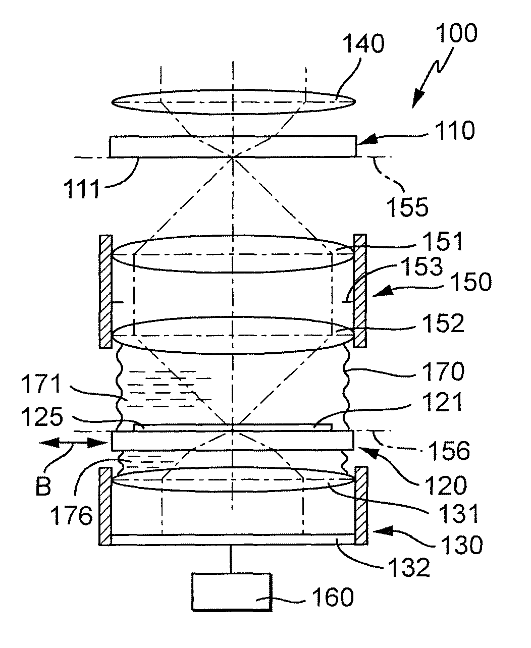
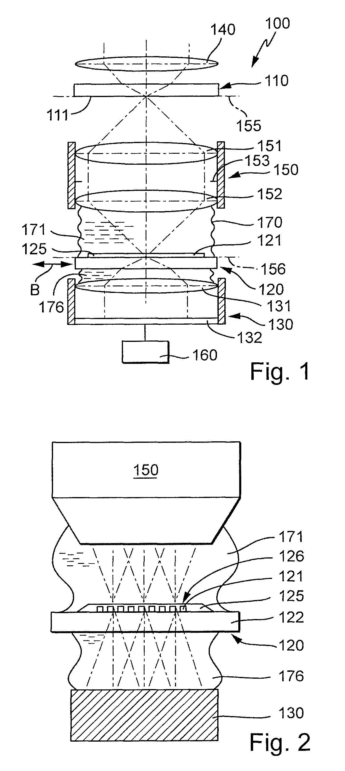
[0047]The measuring system 100 shown schematically in FIG. 1 is used for the optical measurement of a projection objective 150 which is incorporated into a microlithography projection exposure system, which is designed to produce finely structured semiconductor components by means of immersion lithography at an operating wavelength of 193 nm. The projection objective 150, which is built up from a multiplicity of lenses and acts as a reduction objective, is represented schematically by an entry-side lens 151 and an exit-side lens 152 and, during intended use, is used for the purpose of imaging a pattern of a structure-carrying mask (reticle) arranged in its object plane 155 into the image plane 156 of the projection objective, in which there is a light-sensitive layer which is applied to a semiconductor wafer to be structured. For this purpose, the reticle is illuminated with the aid of an illumination system 140 which, from the radiation of a laser serving as primary light source, f...


PUM

PropertyMeasurementUnit
thicknessaaaaaaaaaa
thicknessaaaaaaaaaa
operating wavelengthaaaaaaaaaa

Abstract

A measuring system (100) for the optical measurement of an optical imaging system (150), which is provided to image a pattern arranged in an object surface (155) of the imaging system in an image surface (156) of the imaging system, comprises an object-side structure carrier (110) having an object-side measuring structure (111), to be arranged on the object side of the imaging system; an image-side structure carrier (120) having an image-side measuring structure (121), to be arranged on the image side of the imaging system; the object-side measuring structure and the image-side measuring structure being matched to each other in such a way that, when the object-side measuring structure is imaged onto the image-side measuring structure with the aid of the imaging system, a superposition pattern is produced; and a detector (130) for the locally resolving acquisition of the superposition pattern. The imaging system is designed as an immersion system for imaging with the aid of an immersion liquid (171). A structure carrier to be arranged in the region of the immersion liquid is assigned a protective system (125) in order to increase the resistance of the measuring structure to degradation caused by the immersion liquid. A measurement of immersion systems under immersion conditions is thereby possible without detrimental influence of the immersion liquid on the measuring accuracy.

Description

[0001]This application claims the benefit of U.S. Provisional Application 60 / 576,803 filed on Jun. 4, 2004. The complete disclosure of that provisional application is incorporated into this application by reference.BACKGROUND OF THE INVENTION[0002]1. Field of the Invention[0003]The invention relates to a measuring system for the optical measurement of an optical imaging system which is provided to image a pattern arranged in an object surface of the imaging system into an image surface of the imaging system, the imaging system being designed as an immersion system for imaging with the aid of an immersion liquid arranged on at least one of the object-side and the image-side of the imaging system[0004]2. Description of the Related Prior Art[0005]In many areas in technology and research, optical imaging systems are used, on which increasingly high requirements are placed with respect to their imaging quality. One example is the photolithographic production of semiconductor components a...

Claims


Application Information

Patent Timeline
Patent Type & Authority Patents(United States)
IPC IPC(8): G01B11/02G03F7/20
CPCG03F7/70341G03F7/70591G03F7/70716G01M11/0271G01M11/0214G01M11/0257G03F7/70958Y10T428/31G03F7/20
Inventor MENGEL, MARKUSWEGMANN, ULRICHEHRMANN, ALBRECHTEMER, WOLFGANGCLEMENT, REINERMATHUSSEN, LUDO
Owner CARL ZEISS SMT GMBH
Why Eureka
Try Eureka