Multilevel push pull power converter

a power converter and push-pull technology, applied in the direction of dc circuit to reduce harmonics/ripples, electric variable regulation, instruments, etc., can solve the problem of more dynamic power dissipation, output voltage cannot be zero, and high switching loss

Active Publication Date: 2010-09-14
HARMAN BECKER AUTOMOTIVE SYST
View PDF24 Cites 9 Cited by
  • Summary
  • Abstract
  • Description
  • Claims
  • Application Information

AI Technical Summary

Benefits of technology

[0015]The power converter of the present invention provides a number of advantages. First, it reduces the difference of voltage rectangulars at the secondary side in the converter to either reduce the ripple current or lower the filter impedances without causing a bigger ripple current. Second, it offers more possibilities for energy conversion by generating more voltage levels and facilitating more regulation opportunities. For example, different voltage / current outputs allow various cross regulation. For another example, with cascaded regulation, two switches can be regulated faster while the other two slower. Third, it can process more power or use lower filter impedances with the same input power and the same output ripple current. Particularly compared to prior art converters, the push-pull DC converter of the present invention has the primary switches thereof switched against electrical ground. Interleave of the multiple voltage levels can also be implemented.

Problems solved by technology

If the ripple current needs to be maintained, a higher switching frequency is then required, which would unfortunately bring higher switching losses.
However, as switching frequency is a trade-off between static and dynamic losses (see Fundamentals of Power Electronics, ISBN 0-7923-7270-0), when a higher frequency is applied to the electrical switches, such as MOSFETs, more dynamic power dissipation would occur at them.
This converter has the disadvantage that the output voltage can never be zero and therefore energy is always transferred to the secondary side due to the fixed duty-cycle of the outer switches.
However, the above technologies have several disadvantages, such as switching one of the switches not against electrical ground, having no further regulation possibilities, and being restricted to outputting only four voltage levels.

Method used


Image

  • Multilevel push pull power converter
  • Multilevel push pull power converter
  • Multilevel push pull power converter

Examples


Embodiment Construction

[0041]The present invention is further described in detail with references to the figures illustrating examples of the present invention.

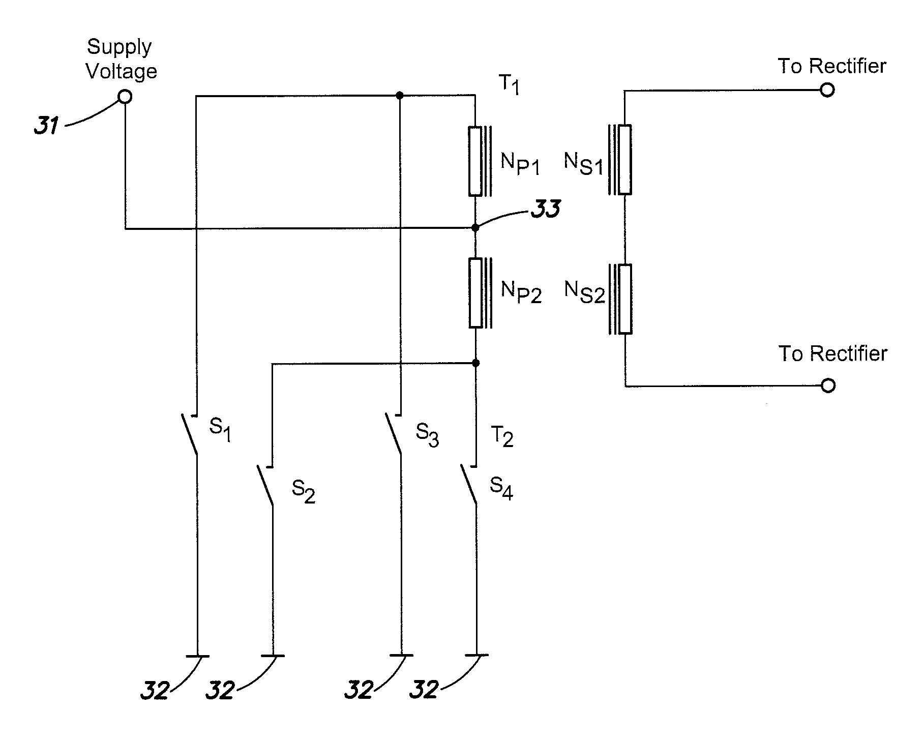
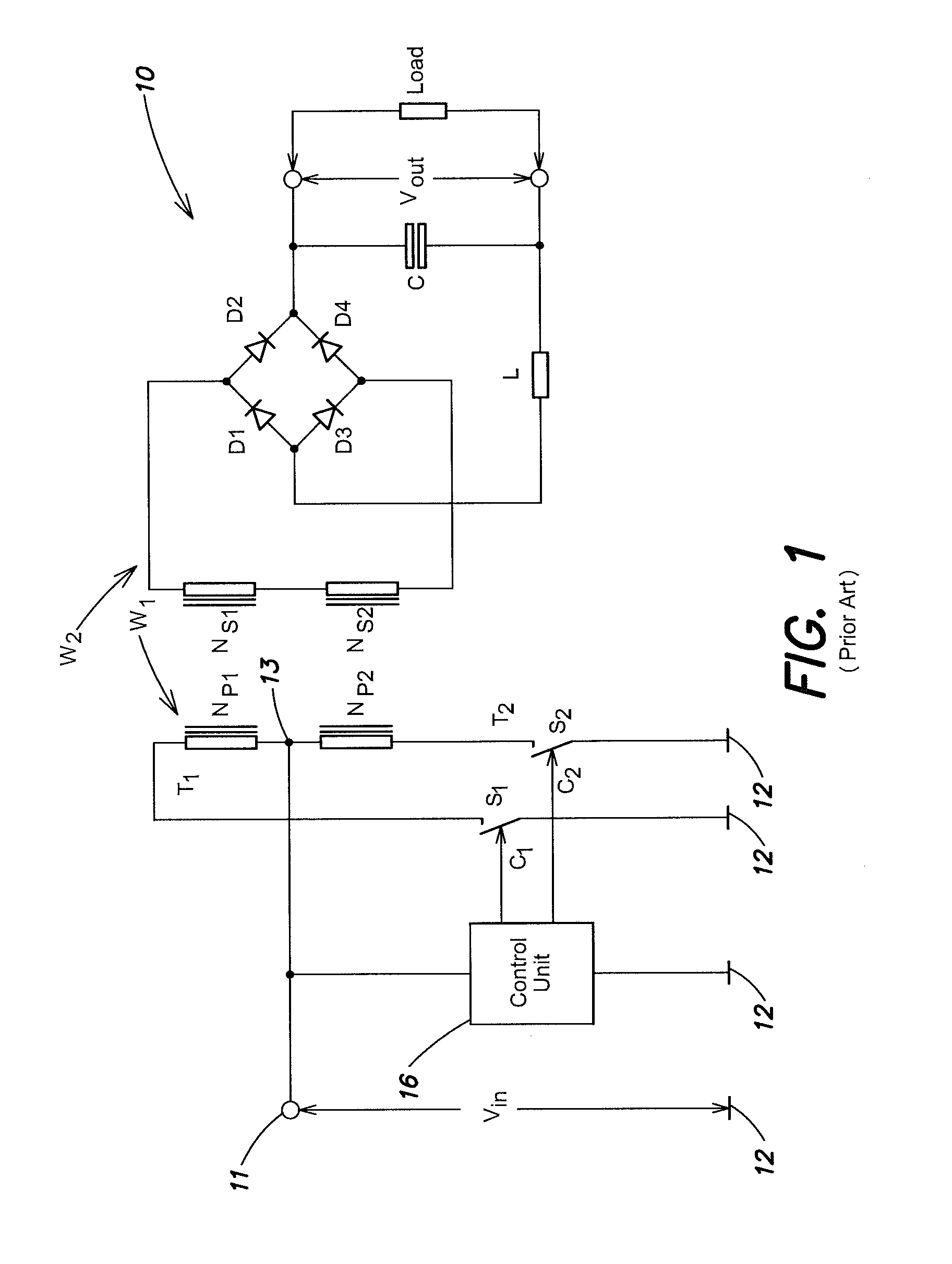
[0042]FIG. 3 is a circuit diagram of a power converter according to an aspect of the present invention. The power converter 30 converts an input voltage Vin into at least one output voltage Vout. Compared to the conventional converter shown in FIG. 1, the power converter 30 includes two additional switches S3 and S4 and two additional primary winding sections Np3 and Np4. Specifically, the power converter 30 includes a first supply potential 31 and a second supply potential 32 established by the input voltage. One of these two supply potentials, here the second potential 32, may be the ground.

[0043]The power converter 30 also includes a primary winding W1 that is divided into four sections Np1, Np2, Np3 and Np4, by three taps33, 34 and 35 arranged between the two end terminals T1 and T2 of the winding. Apart form the center tap 33, which is arrange...


PUM


Abstract

A power converter for converting an input voltage (Vin) into an output voltage (Vout), comprising a first supply potential and a second supply potential established by the input voltage, and at least one primary winding having two terminals, a center tap arranged between the two terminals and connected to the first supply potential, and at least one secondary winding magnetically coupled to the primary winding for providing at least one output voltage (Vout) and a first controllable switch connected between the second supply potential and one terminal of the primary winding and a second controllable switch connected between the second supply potential and the other terminal of the primary winding and a third controllable switch connected between the second supply potential and the one terminal of the primary winding and a fourth controllable switch connected between the second supply potential and the other terminal of the primary winding, and a control unit for controlling the switches such that the first, second, third, and fourth switches are turned on sequentially wherein at any time maximum one switch is turned on.

Description

CLAIM OF PRIORITY[0001]This patent application claims priority to European Patent Application serial number 06 000 971.9 filed on Jan. 18, 2006.FIELD OF THE INVENTION[0002]The present invention relates to a power converter and, in particular, a push-pull direct current to direct current (DC-DC) power converter.RELATED ART[0003]DC-DC power converters are electronic devices that change DC electrical power efficiently from one voltage level to another. Typical industrial applications of DC-DC converters are, for example, where 24V DC from a truck battery is stepped down to 12V DC to run a car radio, where 1.5V from a single cell battery is stepped up to 5V or more to operate some electronic circuitry, or where 12V DC is stepped up to + / −40V to drive a car HiFi amplifier circuitry.[0004]There are many different types of DC-DC power converters, each of which tends to be more suitable for some kinds of applications than for others. One type of DC-DC power converter is the isolating conver...

Claims


Application Information

Patent Timeline
Patent Type & Authority Patents(United States)
IPC IPC(8): H02M3/337
CPCH02M3/3378
Inventor KNOTT, ARNOLD
Owner HARMAN BECKER AUTOMOTIVE SYST
Why Eureka
Try Eureka