Atraumatic anchoring and disengagement mechanism for permanent implant device

a permanent implant device and anchoring mechanism technology, applied in the field of improved thrombosis filters, can solve the problems of strut damage to the lumen wall, double the risk of removal process, and the patient is susceptible to thrombosis formation

Inactive Publication Date: 2010-09-21
LIFESCREEN SCI
View PDF32 Cites 43 Cited by
  • Summary
  • Abstract
  • Description
  • Claims
  • Application Information

AI Technical Summary

Benefits of technology

[0014]In one embodiment of the removable structure for the thrombosis filter, a retracting mechanism, in combination with the recovery mechanism, causes the plurality of positioning struts to be withdrawn from contact with the inner lumen wall and to be deflected into a substantially parallel relationship with the struts arranged longitudinally in the direction of their original deployment.

Problems solved by technology

A laparotomy procedure is a surgical procedure done under general anesthesia, and is susceptible to thrombosis formation due to discontinuance of anti-coagulant therapy prior to such surgery.
This process can occur within two or three weeks, and in prior art filter arrangements renders the filter unremovable by a single percutaneous process without incurring significant vessel trauma.
With the struts deployed outwardly to engage the walls of the lumen, asymmetrical compression of the lumen can cause the struts to be forced together in a manner that causes the struts to do damage to the lumen wall.
Once deployed, the filter is positioned for definitive use and may not thereafter be readily removed.
This removal process doubles the risk to the patient, and due to the small size of the elements, is relatively difficult to accomplish.
The prior art structures do not describe filter structures that are readily removable utilizing a single percutaneous removal procedure.

Method used


Image

  • Atraumatic anchoring and disengagement mechanism for permanent implant device
  • Atraumatic anchoring and disengagement mechanism for permanent implant device
  • Atraumatic anchoring and disengagement mechanism for permanent implant device

Examples


Embodiment Construction

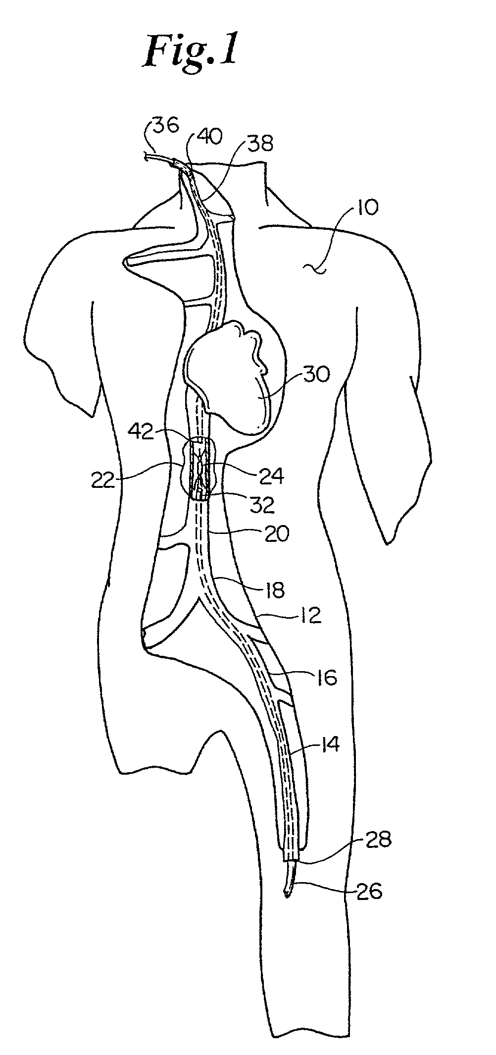
[0052]FIG. 1 is a fragmentary section through a human body from left to right and illustrates a medical procedure of installing the thrombosis filter in the inferior vena cava and removal of the filter by percutaneously entering the venous system at the jugular vein and withdrawing the filter. This illustrates the body 10 with a cutaway portion 12 that exposes a portion of the vascular system. The femoral vein 14 leads to the external iliac vein 16. The common iliac vein 18 leads to the inferior vena cava 20. As illustrated at the cutaway section 22, a filter 24 is dispersed within the inferior vena cava and is held in place by the structure that will be described. As shown, a catheter tube is inserted at incision 28 into the venous system. As it extends toward heart 30, it reaches the inferior vena cava 20 and the filter 24 is deployed. The distal end 32 of the catheter structure 26 is shown after deployment of the filter 24. For withdrawal or removal of filter 24, a recovery mecha...


PUM


Abstract

A recoverable thrombosis filter that may be recoverable by a single recovery procedure. It can include a plurality of thrombosis filtering elements that are shaped in a predetermined manner and which are joined at one end and are deployed about a longitudinal axis to form a generally conical structure. The filtering elements can include shaped ends for engaging an inner lumen wall.

Description

CROSS REFERENCE TO RELATED APPLICATION[0001]This is a continuation of application Ser. No. 08 / 978,403, filed on Nov. 25, 1997 now U.S. Pat. No. 6,447,530, which in turn is a continuation-in-part of application Ser. No. 08 / 942,531, filed Oct. 2, 1997 now abandoned, which in turn is a continuation-in-part of application Ser. No. 08 / 757,827, filed Nov. 27, 1996 now abandoned.TECHNICAL FIELD[0002]The present invention relates to improved thrombosis filters. More particularly, the invention relates to a thrombosis filter that can be percutaneously installed in a selected body lumen at a selected location in the vascular system and is adapted for trapping thrombosis materials or blood clots. Still more particularly, the invention relates to a thrombosis filter that can be percutaneously removed from the vascular system from a single direction.BACKGROUND OF THE INVENTION[0003]Pulmonary embolism is a recognized medical emergency, and may be caused by venous thrombosis. The venous thrombosis...

Claims


Application Information

Patent Timeline
Patent Type & Authority Patents(United States)
IPC IPC(8): A61M29/00A61B17/00A61B17/12A61F2/01A61F2/06
CPCA61F2/01A61F2002/011A61F2002/016A61F2002/8486A61F2230/005A61F2230/0067A61F2/011A61F2/0105A61F2/0103
Inventor OSTROVSKY, ISAACWALLACE, MICHAEL J.KIM, HANNAHSHANK, PETERDIMATTEO, KRISTIAN
Owner LIFESCREEN SCI
Why Eureka
Try Eureka