Air separator conveyor and vision system

a conveyor and air separator technology, applied in the field of inspection systems of articles, can solve the problems of reducing the precision of the inspection process, reducing the accuracy of inspection, so as to achieve the effect of more precision

Inactive Publication Date: 2010-09-21
LOGICAL SYST
View PDF40 Cites 43 Cited by
  • Summary
  • Abstract
  • Description
  • Claims
  • Application Information

AI Technical Summary

Benefits of technology

[0008]In a first embodiment, this invention is a system for accurately determining whether a work piece such as a plastic molded bottle cap is defective from quality norms and removing those defective pieces from a stream of work pieces. The system includes a feed conveyor for serially delivering work pieces where adjacent work pieces are in contact with each other. The feed conveyor delivers these work pieces onto an inspection conveyor that is generally horizontal. Adjustable guide rails and a guide rail cover create a closed passage just large enough for the work pieces to flow through without impediment. The inspection conveyor may also have one or more machined grooves to allow slightly defective work pieces to flow through the passage without dragging or getting stuck.
[0010]The inspection conveyor in one embodiment is generally made with a translucent plastic material that transmits some light. In the middle of the passage, the guide rails and the guide rail cover each have an opening where an inspection station is located. This inspection station includes at least one camera and one light source. The light source can be any kind of light that illuminates the work piece such as a bottle cap, and one embodiment uses an infrared light. The light source is located under the inspection conveyor and lights the underside of each work piece. The camera is located above the inspection conveyor and light source and is oriented perpendicular to the inspection conveyor so that a full image of each work piece can be recorded as the work piece moves through the inspection station. The camera is timely activated by a trigger such a photoelectric switch that determines exactly when a work piece is in position to be photographed.
[0012]A second embodiment of the invention includes all the same elements as the first embodiment, but in this embodiment a portion of the inspection conveyor is replaced with a glass window at the inspection station. In this embodiment the light source and the camera can be switched so that the camera takes images from beneath the work pieces sitting on the inspection conveyor, and the light source illuminates the work pieces from above the inspection conveyor. Alternatively, this second embodiment could allow for two cameras positioned one above and one below the inspection conveyor instead of one camera and a light source. With two cameras, more work pieces that do not transmit light well can be analyzed and inspected. This second embodiment will allow for different kinds of work pieces to be inspected and sorted by this invention.
[0013]This invention overcomes the above-described disadvantages of known vision inspection systems by providing a precision-controlled separation distance and time between each of a series of work pieces such as plastic molded bottle caps. The level of air pressure delivered by the air jet and the air blower as well as the angle of the air holes disposed through the inspection conveyor can all be altered to fit the needs of a specific set of work pieces, thereby giving the current invention much more precision than known gravity-driven inspection systems in a smaller work space. The processing and analyzing rates are not affected by the changes from known systems, as the current invention can handle the inspection of up to 1600 work pieces per minute, depending on the work piece and the air pressure configuration.

Problems solved by technology

During the manufacture of many parts such as plastic molded closure caps, a number of defects in the closure cap may exist which should cause the cap to be rejected.
Examples of defects in such closure caps include a liner which is positioned off-center within the closure, a missing liner, a malformed liner (commonly referred to as a “moon-cut liner”), a cap which is asymmetric or off-round, a cap having an edge broken or flashing on the edge from extraneous plastic material, a pull tab defect on the liner caps with excessively large “gates” resulting from the molding process, or other similar problems.
Such flaws or defects are sometimes produced during the manufacturing process, or as a result of contamination or damages after manufacture but prior to the filling of the container.
While human vision may outperform its automatic equivalent in the ability to analyze very complex, everyday scenes, when it comes to repeated tasks, such as the inspection of plastic molded caps over and over again, a human observer understandably tires, loses concentration, and makes mistakes.
While known vision systems have the above described advantages for inspecting articles such as plastic molded caps and the like, they do have specific and significant limitations.
One problem in efficiently creating photographic records of each plastic molded cap is providing enough separation between adjacent caps on a conveyor leading to the vision system.
This process is effective, but often requires a relatively large space and floor space in most industrial settings is limited.

Method used


Image

  • Air separator conveyor and vision system
  • Air separator conveyor and vision system
  • Air separator conveyor and vision system

Examples


first embodiment

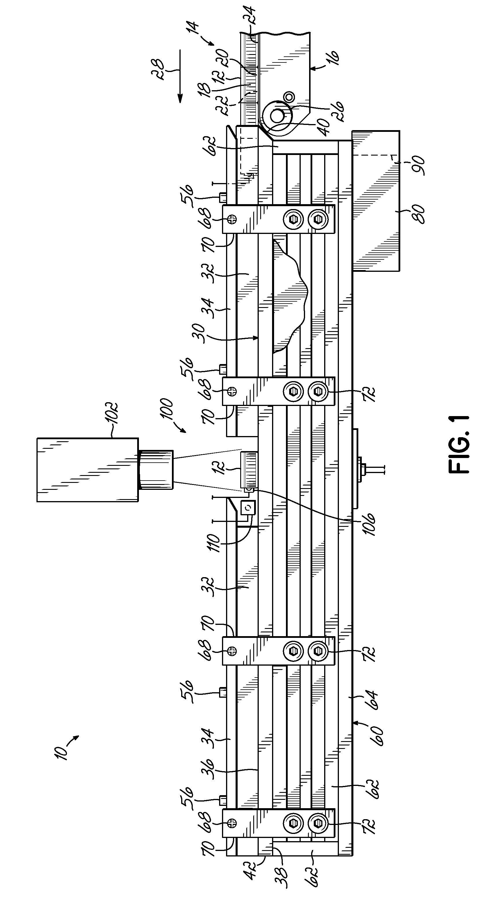
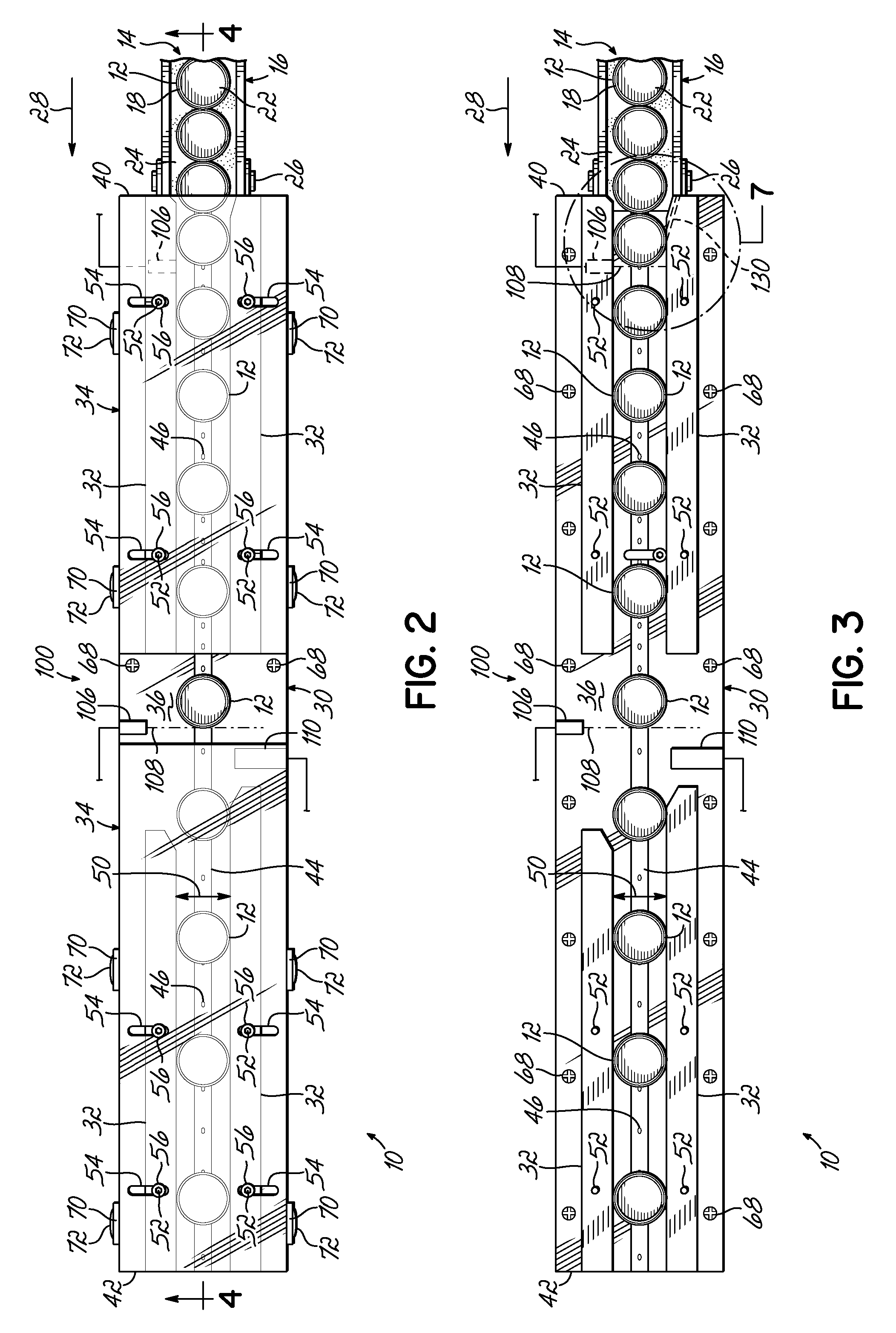
[0026]Referring to FIGS. 1-9, this invention of an air conveyor vision inspection system and associated method for industrial work pieces is shown. The inspection system 10 is used to individually inspect each of a number of work pieces 12 and determine if each work piece 12 meets quality control standards. These work pieces 12 can be any variety of industrially produced items, such as plastic molded bottle caps as shown in FIGS. 1-11. For bottle caps 12, a batch 14 of the caps 12 is created using an injection molding process and then delivered by a feed conveyor 16 or other means to the inspection system 10. Bottle caps 12 made in this manner typically include a peripheral skirt 18 projecting from a base or end wall 20 and a liner 22 may also be inserted into the cap 12.

[0027]As shown in FIG. 1, the inspection system 10 processes work pieces or caps 12 from a feed conveyor 16, which comprises a belt 24 trained to travel around at least two rotating rollers 26 (of which one is shown...

second embodiment

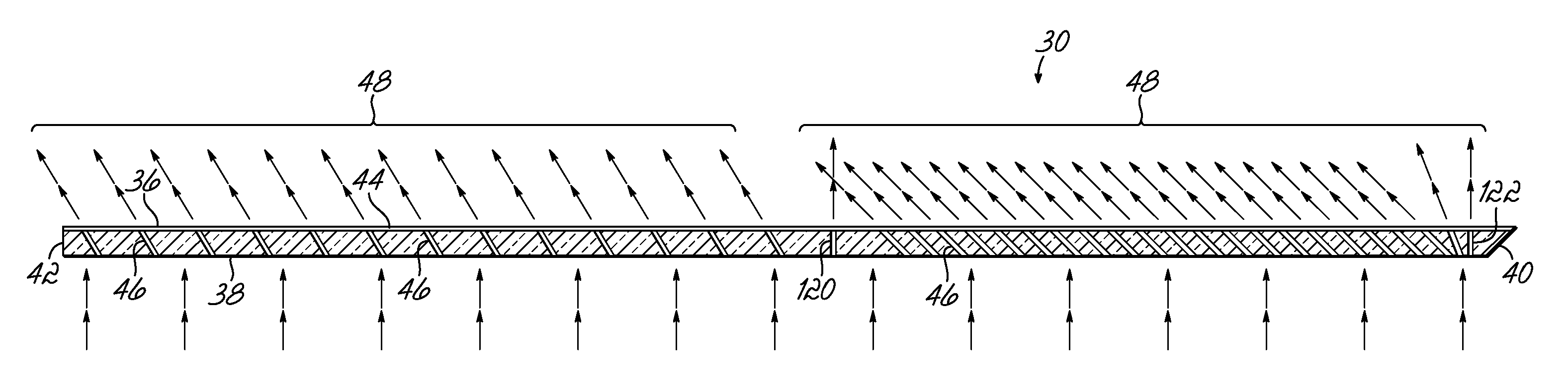
[0037]this invention is shown in FIGS. 10-11. The second embodiment contains all the elements as the first embodiment described in detail above and in FIGS. 1-9, as well as one additional feature. Instead of the inspection conveyor 30 being made completely out of translucent plastic material, an inspection window 200 is placed in the inspection conveyor 30 instead of plastic material at the inspection station 100. This window 200 can be used where the inspection conveyor 30, guide rails 32, and guide rail cover 34 are each made of a different material than transparent or translucent plastic. The window 200 preferably produces a high diffusion of light and may be created out of glass such as opal glass. The glass segment of the inspection conveyor 30 in this embodiment does not interfere with or change the orientation of air holes 46 extending throughout the inspection conveyor 30.

[0038]The second embodiment also enables a user to set up the inspection station elements in different w...


PUM

PropertyMeasurementUnit
diameteraaaaaaaaaa
angleaaaaaaaaaa
inner diametersaaaaaaaaaa

Abstract

A system for accurately determining whether a work piece such as a plastic molded bottle cap is defective from quality norms and removing those defective pieces from a stream of work pieces includes a feed conveyor for serially delivering work pieces where adjacent work pieces are in contact with each other. The feed conveyor delivers these work pieces onto an inspection conveyor with a plurality of air holes. Air is forced through the air holes to impinge upon the work piece and thus rapidly accelerate them away from the adjacent work piece it was in contact with and move through an inspection station. An air blower provides pressurized air through the air holes to continue accelerating and separating the work pieces as they move. The inspection station includes a camera to image each work piece. The camera communicates these images to a processing unit such as a computer that can rapidly compare the image to a set of quality control standards each work piece should meet.

Description

FIELD OF THE INVENTION[0001]This invention relates to article inspection systems and particularly to vision systems for inspecting work pieces such as plastic molded closure caps for containers and the like.BACKGROUND[0002]During the manufacture of many parts such as plastic molded closure caps, a number of defects in the closure cap may exist which should cause the cap to be rejected. Commonly, closure caps of this type have a liner inserted therein against the inner surface of an end wall of the cap. Typically, the cap has a skirt projecting annularly from the peripheral rim of the end wall and the skirt may include a closure or sealing mechanism such as threads for cooperation with mating threads around the neck of a bottle, container, or the like. Examples of defects in such closure caps include a liner which is positioned off-center within the closure, a missing liner, a malformed liner (commonly referred to as a “moon-cut liner”), a cap which is asymmetric or off-round, a cap ...

Claims


Application Information

Patent Timeline
Patent Type & Authority Patents(United States)
IPC IPC(8): B07C5/00
CPCB07C5/3422G01N21/95G01N21/88B07C5/365G01N21/909
Inventor GOCHAR, JR., JOSEPH P.
Owner LOGICAL SYST
Why Eureka
Try Eureka