Mass spectrometer and mass spectrometry method

a mass spectrometer and mass spectrometry technology, applied in the direction of isotope separation, electric discharge tube, particle separator tube, etc., can solve the problems of inability to achieve dual operation and drop in ejection efficiency, and achieve high mass resolving power and high ejection efficiency

Active Publication Date: 2010-09-21
HITACHI HIGH-TECH CORP
View PDF5 Cites 9 Cited by
  • Summary
  • Abstract
  • Description
  • Claims
  • Application Information

AI Technical Summary

Benefits of technology

[0009]The object of the present invention is to provide a mass spectrometer capable of operating as a linear trap with high ejection efficiency and also a low spatial spread of ejected ions, and capable of switching to operate as a mass filter with high mass resolving power. Achieving a mass spectrometer with the above performance would also improve the duty cycle.
[0015]Also, when operating to pass ions selectively by mass, control is exerted to eliminate the difference in voltage potential between the second lens and the multipole rod lens. Also, the voltage on the multipole rod lens is changed to allow the detector to acquire the mass spectrum.
[0016]The mass spectrometry method of this invention is characterized by operation to switch between: a process utilizing a second lens installed between one end and the other end of a multipole rod lens to trap and oscillate the supplied ions in a section of the multipole rod lens, and regulating the voltage of the second lens to eject the oscillated ions along the center axis of the multipole rod lens; and a process for filtering the supplied ions according to mass by exerting control to eliminate the difference in voltage potential between the second lens and multipole rod lens.
[0017]This invention achieves a mass spectrometer capable switching between operation as a linear trap with high ejection efficiency and operation as a mass filter with high mass resolving power.

Problems solved by technology

Increasing the trap length as a countermeasure causes a drop in ejection efficiency.
On the other hand a long rod is required to obtain high resolving power when operated as a quadrupole mass filter so dual operation is impossible to achieve.

Method used


Image

  • Mass spectrometer and mass spectrometry method
  • Mass spectrometer and mass spectrometry method
  • Mass spectrometer and mass spectrometry method

Examples


first embodiment

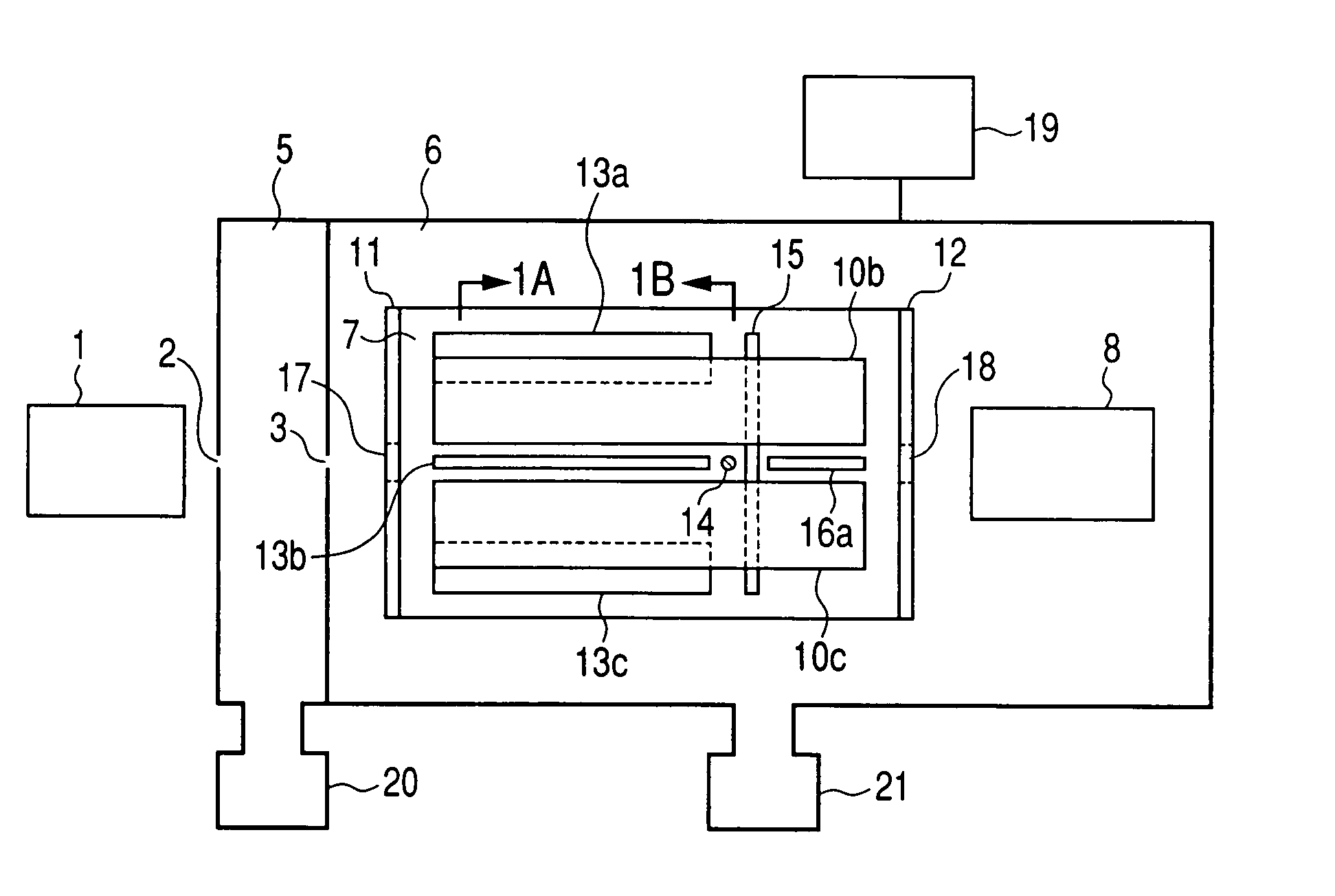
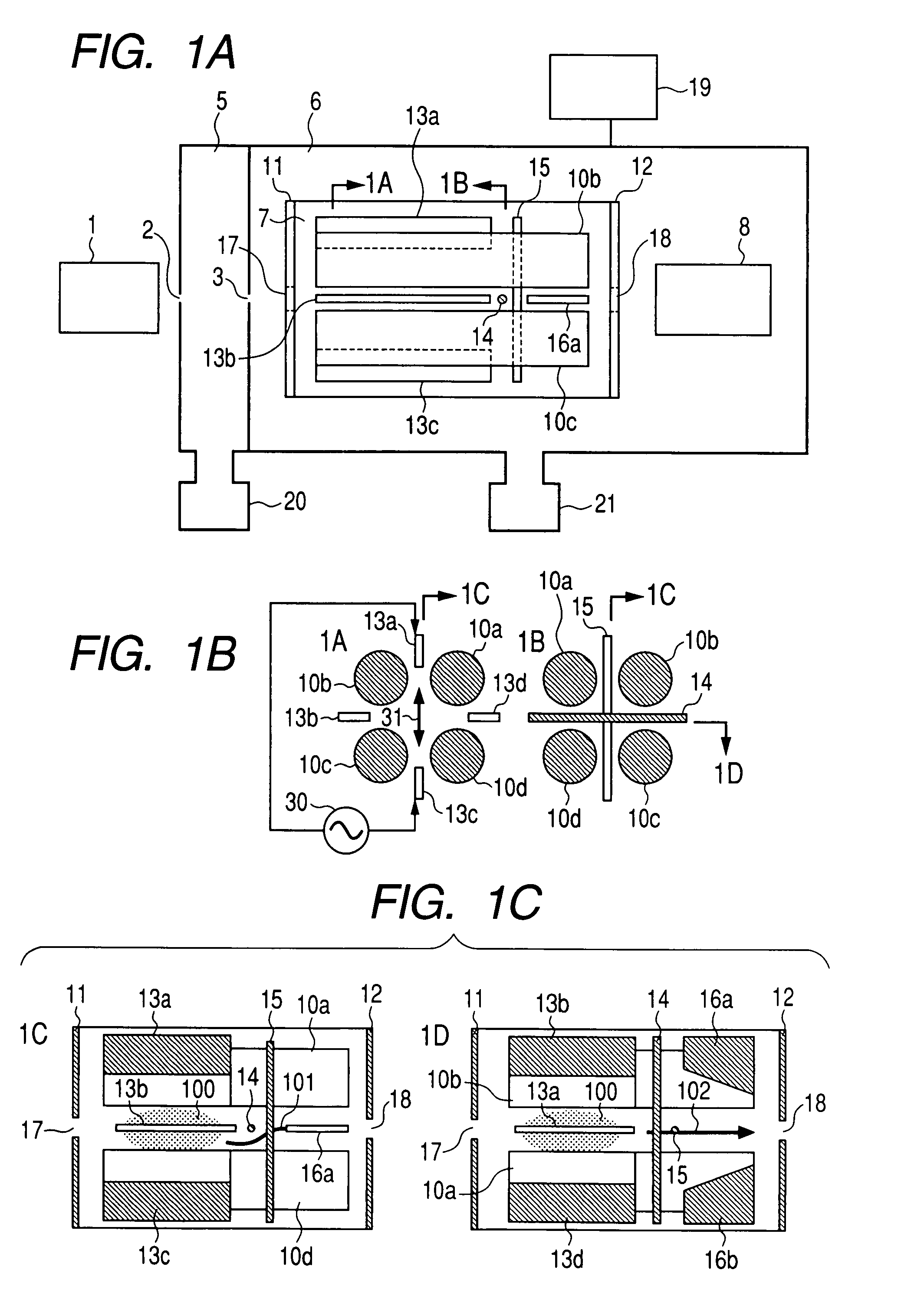
[0037]FIG. 1 is diagrams of the mass spectrometer of the method for this invention. FIG. 1A is a block diagram of the overall mass spectrometer. FIG. 1B is a cross sectional view of the device along the radial direction. FIG. 1C is a cross sectional view along the axis of the linear trap. FIGS. 1A, 1B, and 1C are cross sectional views as seen from the direction of the arrow. Ions generated in an ion source 1 such as an electro-spray ion source, atmospheric pressure chemical ionization source, atmospheric pressure photo-ionization source, atmospheric pressure matrix assisted laser desorption ionization source, matrix assisted laser desorption ionization source, are supplied via an aperture 2 into a differential exhaust portion 5. A pump 20 exhausts the differential exhaust portion. The ions from the differential exhaust portion pass through an aperture 3 and are supplied into an analyzer 6. The pump 21 exhausts the analyzer section to maintain it at a 10−4 Torr or lower (1.3×10⁻² Pa ...

second embodiment

[0052]FIG. 7 is diagrams of the mass spectrometer of this method. 7A in FIG. 7 shows a cross sectional view. The device structure up to the ions arriving at the mass analyzer unit and the structure from the mass analysis unit onward is the same as the first embodiment so a description is omitted here.

[0053]Linear trap operation is described first. During operation as a linear trap, buffer gas is supplied to the mass analyzer unit 7 and maintained at 10−4 Torr-10−2 Torr (1.3×10⁻² Pa−1.3 Pa). The trap lens 14 may utilize a thin-plated lens (electrode) or a wire-shaped lens (electrode). The wire-shaped lens possesses lower ion transmittance loss but the lens shape is more difficult to manufacture.

[0054]FIG. 8 shows the measurement sequence. Measurement was performed in three sequences. A trap RF voltage (amplitude 100 volts-5,000 volts, frequency 500 kHz-2 MHz) was applied to the quadrupole rod lens 10 during the trap period.

[0055]Typical voltages applied to the other lenses are; setti...

third embodiment

[0058]FIG. 9 is a structural diagram of the mass spectrometer of this method. 8A in FIG. 9 indicates a cross sectional view. The device structure up to the ions arriving at the mass analyzer unit and the device structure from the mass analysis unit onward is the same as the first embodiment so a description is omitted here.

[0059]Operating the spectrometer as a linear trap is described first. During operation as a linear trap, buffer gas is supplied to the mass analyzer unit 7 and maintained at 10−4 Torr -10−2 Torr (1.3×10⁻² Pa−1.3 Pa. The trap lens 14 may utilize a thin-plated lens (electrode) or a wire-shaped lens (electrode). The wire-shaped lens possesses lower ion transmittance loss but the lens shape is more difficult to manufacture. Except for the fact that the supplemental AC voltage is applied to the vane lens 13 and not the quadrupole rod lens 10, the measurement sequence of the third embodiment is identical to the measurement sequence of the second embodiment. Measurement ...


PUM


Abstract

A mass spectrometer that is switchable to operate as a linear trap or as a mass filter, and attaining both high ejection efficiency when operated as a linear trap and high mass resolving power when operated as a mass filter. A mass spectrometer includes an ion source for ionizing a sample, a linear trap quadrupole rod lens supplied with ionized ions, a trap electrode for forming a potential to trap the supplied ions between one end of the quadrupole lens and the other end, a control unit to regulate the trap lens voltage, and a mass analyzer or detector to detect ions ejected from the linear trap, and characterized in switching between an operation where the supplied ions are trapped in a section quadrupole rod lens and ejected by the controller unit regulating the trap electrode voltage; and an operation where ions are selective passed through according to their mass. The ejection efficiency when operated as an ion trap, and the mass resolving power when operated as a quadrupole mass filter are vastly improved compared to conventional methods.

Description

CLAIM OF PRIORITY[0001]The present invention claims priority from Japanese application JP 2006-316462 filed on Nov. 24, 2006, the content of which is hereby incorporated by reference into this application.FIELD OF THE INVENTION[0002]The present invention relates to a mass spectrometer and mass spectrometry method thereof.BACKGROUND OF THE INVENTION[0003]The linear trap interior is capable of MSn analysis and widely utilized in proteome analysis. Mass selective ejection of ions trapped inside linear ion trap performed in the related art as described next.[0004]An example of technology for mass selective ion ejection from the linear trap is disclosed in U.S. Pat. No. 5,420,425. After accumulating axially injected ions inside the linear trap, ion selection and ion disassociation performed as needed. A supplemental AC field is then applied across an opposing pair of quadrupole rod lenses, and specified ions can be excited along the radial direction. Ions are then selectively ejected tow...

Claims


Application Information

Patent Timeline
Patent Type & Authority Patents(United States)
IPC IPC(8): H01J49/00
CPCH01J49/4215H01J49/4225
Inventor SUGIYAMA, MASUYUKIHASHIMOTO, YUICHIROHASEGAWA, HIDEKIWAKI, IZUMI
Owner HITACHI HIGH-TECH CORP
Why Eureka
Try Eureka