Method and apparatus for reducing fringe interference of light

a fringe interference and light technology, applied in the field of light fringe interference reduction methods and apparatuses, can solve the problems of affecting the sensitivity of the sample, affecting the absorption induced signal of the sample, and the reflections causing the fringe interference are extremely difficult to eliminate completely, so as to reduce the fringe interference

Active Publication Date: 2010-09-21
SIEMENS AG
View PDF5 Cites 10 Cited by
  • Summary
  • Abstract
  • Description
  • Claims
  • Application Information

AI Technical Summary

Benefits of technology

[0007]Therefore, the invention seeks to provide a more effective method and apparatus for reducing fringe interference.
[0010]In accordance with the invention the optical path length of the passive cavity is varied with a Gaussian distribution, where the standard deviation is at least one-quarter of the light's wavelength, preferably at least one-third wavelength and more preferably less than one wavelength. Thus, compared to the triangle modulation which needs vibration amplitudes over several laser wavelengths, an efficient etalon averaging is obtained already at amplitudes following a Gaussian (normal) distribution with a standard deviation slightly above one-quarter wavelength. Another advantage is that, due to character of noise modulation, there is no need of amplitude and phase control of the modulating waveform, thus allowing much simpler hardware design.

Problems solved by technology

Unfortunately, sensitivity is usually severely limited by the presence of interference fringes (etalon fringes) which appear as the narrow bandwidth laser is tuned through the range of the desired absorption signal.
The reflections causing the interference fringes are extremely difficult to eliminate completely even with high quality anti-reflection coatings and careful optical alignment.
These fringes, even when very weak, can easily overwhelm the absorption induced signal from the sample.
Unfortunately, this approach has two drawbacks.
Firstly, generation of a triangular waveform requires a broadband driver and imposes high requirements on the electromechanical setup.
Secondly, in practice, the vibration amplitude of the element has to be more than 15 laser wavelengths to obtain a sufficient reduction of the etalon effect.
This becomes especially impractical when the longer laser wavelengths are used thus imposing higher power consumption and putting higher demand on the mechanical components (for example, standard piezo-transducers have limited length expansion capabilities).
Moreover, unwanted displacement / defocusing of the laser beam may appear when the position of the element oscillates with large amplitudes.

Method used


Image

  • Method and apparatus for reducing fringe interference of light
  • Method and apparatus for reducing fringe interference of light
  • Method and apparatus for reducing fringe interference of light

Examples


Embodiment Construction

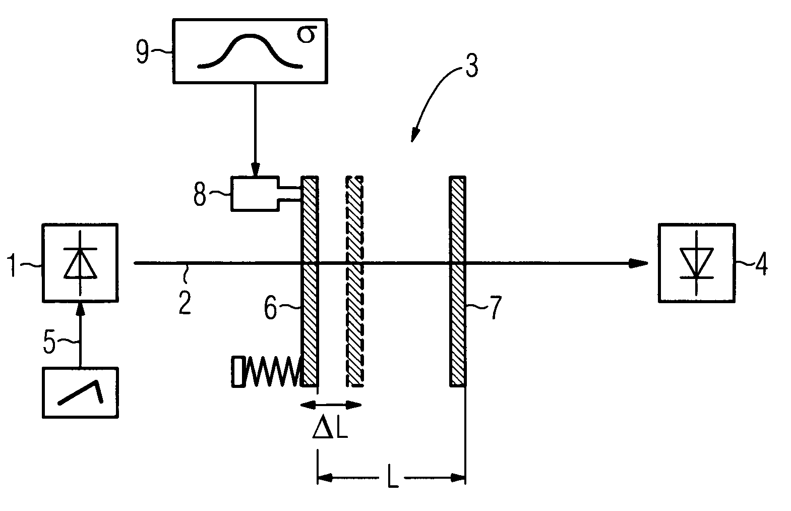
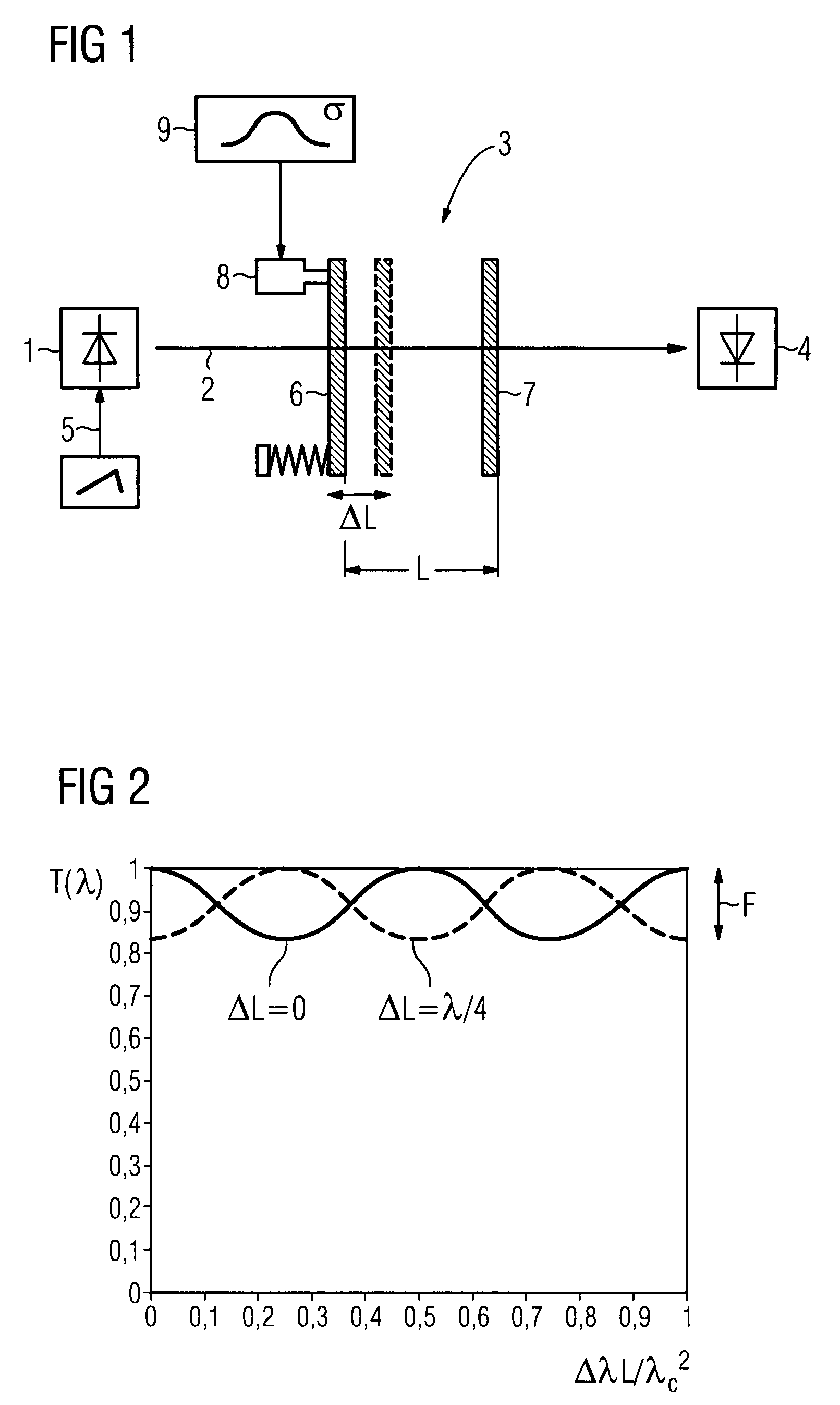
[0017]FIG. 1 shows, as an example for the apparatus according to the invention, a laser spectrometer including a frequency tunable laser 1 for generating a laser beam 2 which passes through an optical system 3 onto an optical detector 4. The optical system 3 comprises, inter alia, a sample cell (not shown) containing a trace gas species in a gas mixture. The laser 1 is modulated with a triangular signal 5 in order to sweep the laser wavelength across specific absorption lines of the trace gas to be determined. The signal received at the optical detector 4 is demodulated to obtain an absorption induced signal.

[0018]Partially reflecting optical surfaces of the sample cell and of other optical elements of the optical system 3, such as windows or lenses, form a passive optical cavity (etalon) which is here represented by a pair of plane parallel partially reflecting planes 6 and 7 at a distance L. This etalon may create the so-called etalon effect which is a dominating source of disturb...


PUM


Abstract

A method for reducing fringe interference of light created in a passive cavity defined by partially reflecting optical surfaces, wherein the optical path length of the cavity is varied with a Gaussian distribution, where the standard deviation is at least one-quarter of the light's wavelength.

Description

CROSS REFERENCE TO RELATED APPLICATIONS[0001]This application claims priority of European Patent Office application No. 06024845.7 EP filed Nov. 30, 2006, which is incorporated by reference herein in its entirety.FIELD OF INVENTION[0002]The invention relates to a method for reducing fringe interference of light created in a passive cavity defined by partially reflecting optical surfaces, wherein the optical path length of the cavity is varied.[0003]The invention further relates to a corresponding apparatus.BACKGROUND OF INVENTION[0004]Laser absorption spectroscopy offers high speed and high precision capabilities for detection of numerous trace gas species in gas mixtures at atmospheric pressure with a small cross sensitivity towards other gas components. Tunable diode laser spectrometers are particularly suited to high sensitivity studies, in part because they may be frequency modulated to reduce low frequency laser noise and electronic noise. A typical spectrometer includes a freq...

Claims


Application Information

Patent Timeline
Patent Type & Authority Patents(United States)
IPC IPC(8): G01B11/02
CPCG01J3/02G01J3/0262G01J3/4338G01N21/0303G01N21/39G01N2021/0389G01N21/1717G01N2021/1723G01N2021/1729
Inventor KLUCZYNSKI, PAWEL
Owner SIEMENS AG
Why Eureka
Try Eureka