
System and method for combustion-air modulation of a gas-fired heating system

a technology of gas-fired heating and combustion air, which is applied in the direction of combustion regulation, fuel supply regulation, pretreatment/pretreatment, etc., can solve the problems of limiting the actual control of the ratio of fuel to air, the range of fuel input modulation of the system is generally limited, and the heaters of the past suffer from a loss of thermal efficiency. , to achieve the effect of improving the thermal efficiency and combustion quality of the heating system

Inactive Publication Date: 2010-09-28
REZNOR
View PDF19 Cites 9 Cited by
  • Summary
  • Abstract
  • Description
  • Claims
  • Application Information

AI Technical Summary

Benefits of technology

Improves thermal efficiency and combustion quality by maintaining a consistent fuel-gas to air ratio, achieving efficiency of at least 80% across a broad modulation range, and ensuring reliable ignition.

Problems solved by technology

This type of system generally has a limited range of fuel-input modulation.
In addition, these contemporary heaters suffer from a loss of thermal efficiency as the fuel-input rate is reduced below their full fuel-input rate.
Typically, however, the damper has only a few static positions available, which limits the actual control over the ratio of fuel to air.
However, these systems are complex and costly, requiring accurate sensor systems, flow control devices such as mechanical jackshafts, and the application of algorithms and control units to regulate the thermal efficiency.
Such systems are conventionally used in conjunction with power burners, which utilize so-called “drum and tube” type heat exchangers as known to those skilled in the art, and are not very amenable for use with tubular, clamshell, serpentine or other heat exchangers.
However, the accuracy of measuring these low negative pressures is limited and adversely affects the ability to accurately control the fuel-gas flow rate.
Subsequently, the accuracy to which the air to fuel gas ratio and, subsequently, the thermal efficiency is limited in conventional modulating heating systems.

Method used


Image

  • System and method for combustion-air modulation of a gas-fired heating system
  • System and method for combustion-air modulation of a gas-fired heating system
  • System and method for combustion-air modulation of a gas-fired heating system

Examples


Embodiment Construction

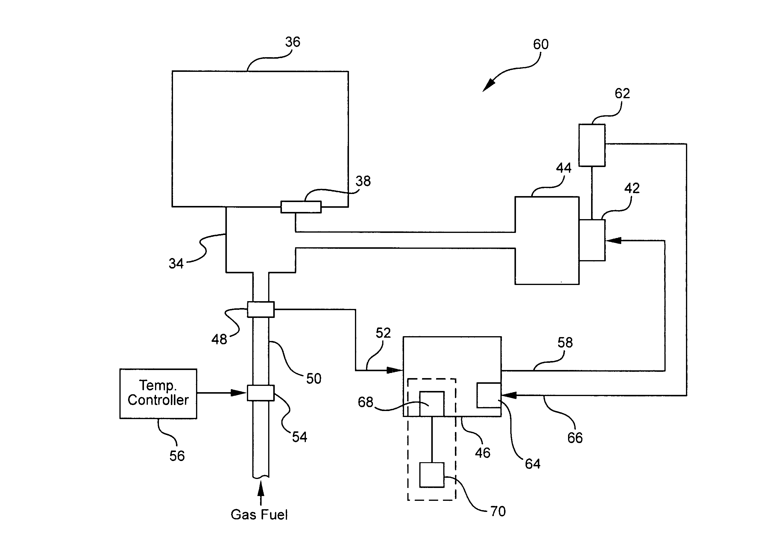
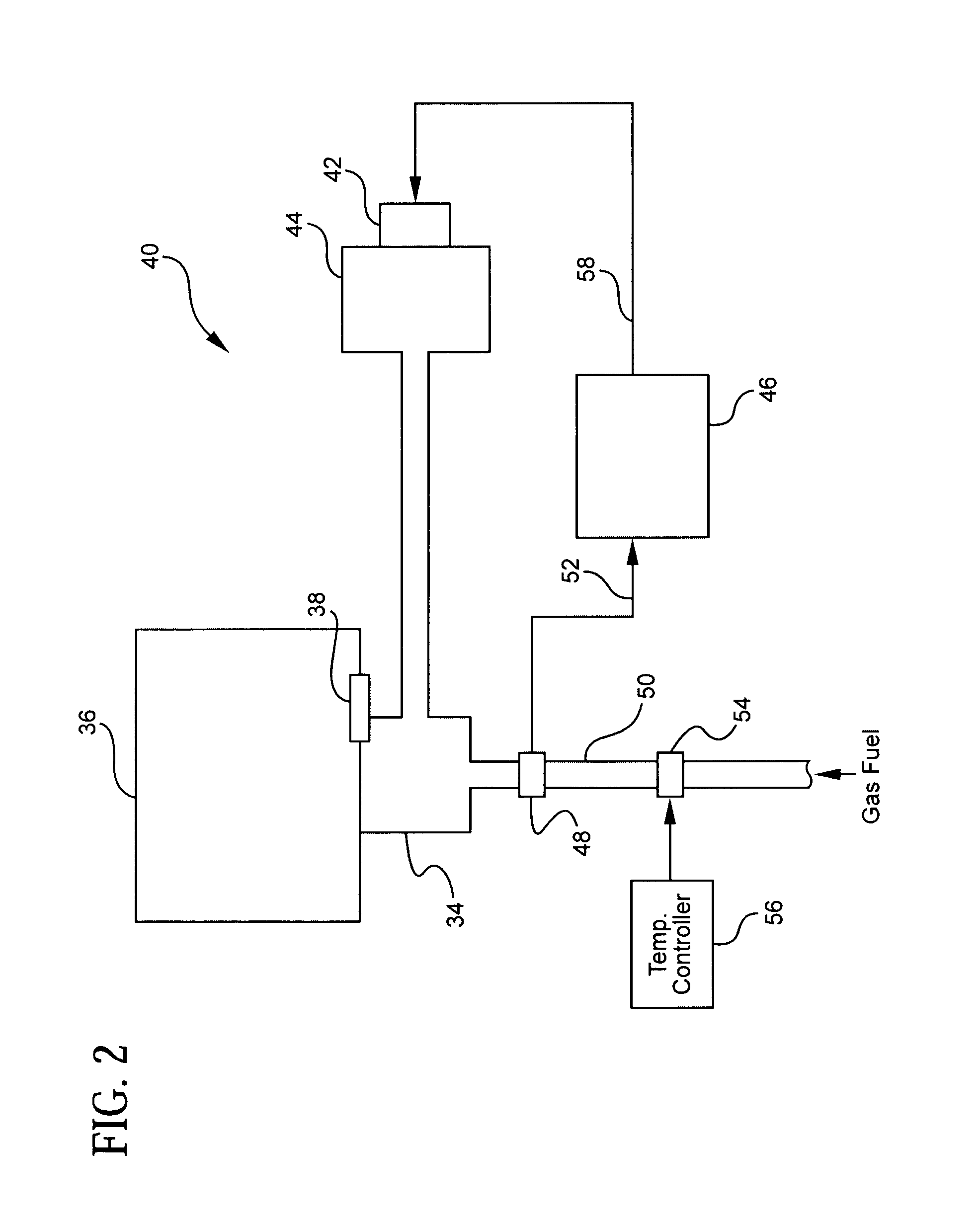
[0025]The present invention provides a method and system for modulating the combustion-air supply in a gas-fired heating system in order to provide improved thermal efficiency. Such heating systems may include, for example, furnace or make-up air systems, or space heaters.

[0026]Conventional modulating gas-fired burners exhibit improved thermal efficiency, combustion quality, and ignition reliability, by modulating the fuel-gas flow in response to the flow rate of combustion air. However, the ability to accurately control the fuel-gas flow is negatively affected by the low negative pressures of the combustion air flow measurements. As a result, it is often difficult to maintain good thermal efficiency over a broad modulation range in conventional modulating gas fired burners.

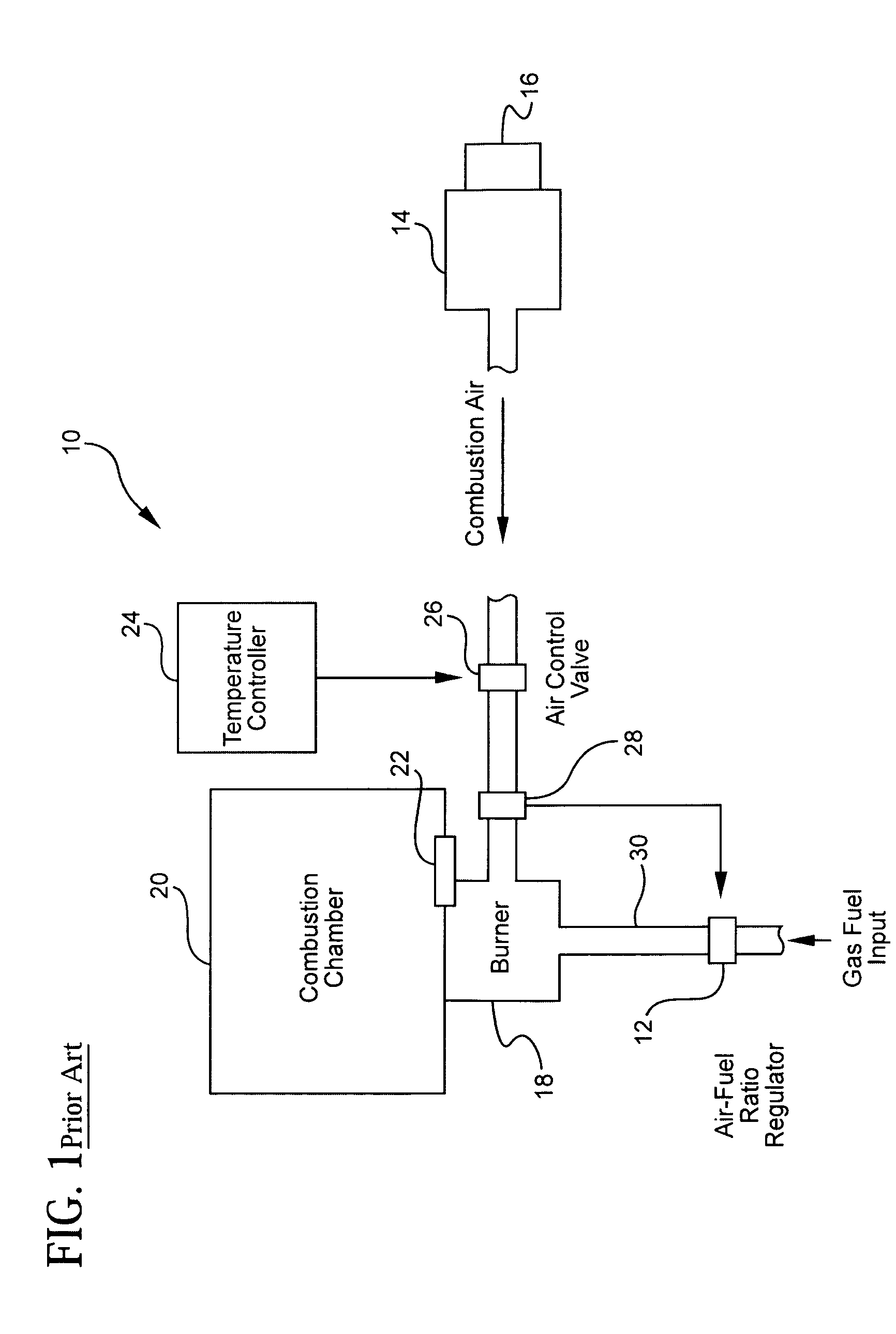
[0027]Referring to FIG. 1, a typical prior art variable fuel-input rate system 10 includes a valve or regulator 12 for varying the fuel-input rate, a combustion air blower 14 or other means for providing combusti...


PUM


Abstract

A system and method for providing a gas-fired heating system with improved thermal efficiency includes modulating a quantity of combustion air flow to a combustion mixture in response to a measured change in fuel-gas pressure using a DC (e.g., brushless) motor to drive a combustion air blower. A pressure transducer in a manifold transporting fuel-gas into the combustion mixture outputs a signal proportional to the measured pressure to the motor. The motor speed and thus the resultant quantity of combustion air flow are modulated in proportion to the quantity of fuel-gas to the mixture. Accordingly, a constant fuel-gas to combustion air ratio is maintained. The system and method may further provide for adjusting the output signal to accommodate measured intake air temperature, and / or measured atmospheric pressure in order to maintain a constant, good thermal efficiency (preferably ≧80%) regardless of air temperature and altitude at the system's installation location.

Description

BACKGROUND OF THE INVENTION[0001]The present invention relates generally to improving the thermal efficiency of heaters or furnaces and, more particularly, to modulating or controlling combustion air flow in relation to the fuel-gas flow in a gas-fired combustion system.[0002]Gas-fired heating systems such as furnace or make-up air systems, or space heaters, typically take in outside air, heat it to a temperature set by a thermostat, and discharge the heated air inside the building. Contemporary heating systems, for example, furnaces for space heating or make-up air heating, are generally equipped with fuel valves which can be used to modulate the fuel-input rate to the heater in order to maintain a stable and controlled temperature. This type of system generally has a limited range of fuel-input modulation. In addition, these contemporary heaters suffer from a loss of thermal efficiency as the fuel-input rate is reduced below their full fuel-input rate.[0003]Alternatively, such con...

Claims


Application Information

Patent Timeline
Patent Type & Authority Patents(United States)
IPC IPC(8): F23N1/02
CPCF23N1/025F23N3/082F23N2005/185F23N2021/10F23N2025/06F23N2025/08F23N2221/10F23N2225/06F23N2225/08
Inventor SPECHT, WERNER
Owner REZNOR
Learn More