
Photomask for double exposure and double exposure method using the same

a double exposure and photomask technology, applied in the field of double exposure photomasks, can solve the problems of defective photomask patterns, deterioration of yields in the manufacture, and difficulty in reducing the line width and line spacing of photomasks below a certain level via single exposure processes, so as to reduce yields and cycle time. , the effect of reducing the yield

Inactive Publication Date: 2010-10-05
SK HYNIX INC
View PDF10 Cites 0 Cited by
  • Summary
  • Abstract
  • Description
  • Claims
  • Application Information

AI Technical Summary

Benefits of technology

The patent describes a photomask for a double exposure process used in the manufacture of integrated circuits. The photomask has two regions divided by a first direction, and a second direction that is perpendicular to the first direction. The mask includes two mask patterns that are formed on the regions, with one pattern in each direction. The mask is designed to minimize yield reduction and cycle time due to misalignment of the mask. The double exposure lithography process using this photomask results in a finer photoresist pattern on the semiconductor wafer. The technical effect of this invention is to improve the accuracy and efficiency of the double exposure process in the manufacture of integrated circuits.

Problems solved by technology

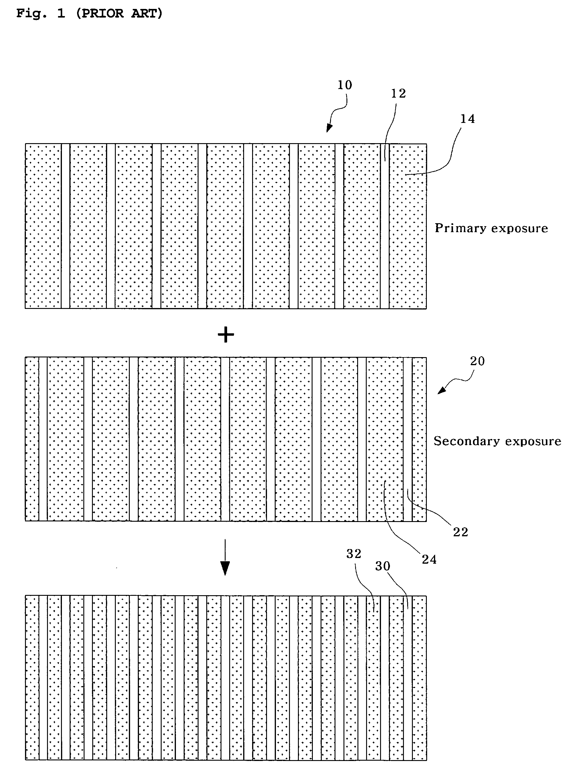
However, due to the resolution limit caused by the diffraction of light in photolithography exposure process, it has been difficult to reduce the line width and line-spacing of the photoresist pattern below a certain level via a single exposure process.
Since such a defective photoresist pattern often results in defective semiconductor devices, defective photoresist patterns are a major factor in the deterioration of yields in the manufacture of semiconductor device.
In particular, as the line-spacing of the photoresist pattern on the semiconductor wafer becomes narrower, this problem is greatly exacerbated.

Method used


Image

  • Photomask for double exposure and double exposure method using the same
  • Photomask for double exposure and double exposure method using the same
  • Photomask for double exposure and double exposure method using the same

Examples


Embodiment Construction

[0039]Exemplary embodiments of the present invention will be described in detail with reference to the accompanying drawings.

[0040]A photomask for a double exposure process and a double exposure method using the same according to an embodiment of the invention will be described with reference to the drawings such that those skilled in the art may practice the present invention according to the teachings of the description.

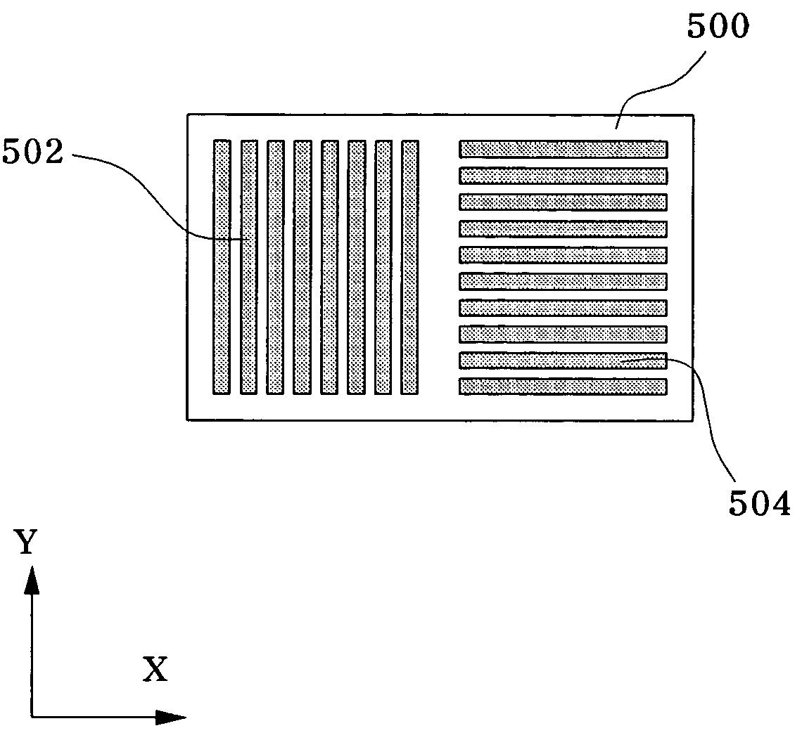
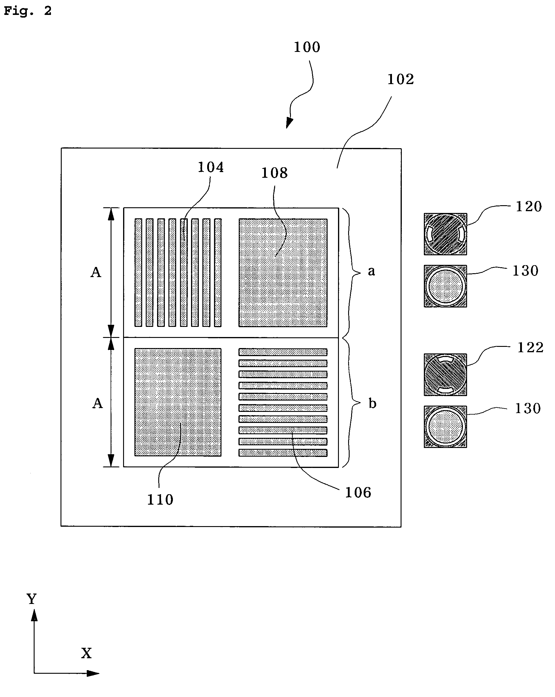
[0041]FIG. 2 is an exemplary simplified schematic view illustrating a photomask for a double exposure process in accordance with a specific embodiment of the invention, and FIG. 6 is an exemplary simplified schematic view illustrating a photoresist pattern formed on a semiconductor wafer after a double exposure process has been performed using the photomasks of FIGS. 2 to 5.

[0042]Referring to FIG. 2, a photomask 100 used in a double exposure process is provided, with photomask 100 being arranged to move in first and second directions. The first and second direction...


PUM

PropertyMeasurementUnit
densityaaaaaaaaaa
sizeaaaaaaaaaa
circuit densityaaaaaaaaaa

Abstract

A photomask for double exposure, and a double exposure method using the same are disclosed. The photomask for double exposure comprises a mask substrate divided into first and second regions equally arranged to upper and lower sides on different sides, respectively, a first mask pattern formed on the first region of the mask substrate, and a second mask pattern formed on the second region of the mask substrate. The photomask and the double exposure method using the same enable a finer photoresist pattern to be formed on a semiconductor wafer, while minimizing reduction in yield and productivity due to misalignment and replacement.

Description

CROSS-REFERENCES TO RELATED APPLICATIONS[0001]The present application claims priority to Korean Patent Application No. 10-2005-0081972, filed on Sep. 3, 2005, which is incorporated by reference.BACKGROUND OF THE INVENTION[0002]The present invention relates to a photomask for a double exposure process and a double exposure method using the same which enables a finer photoresist pattern to be formed through the double exposure process while minimizing yield reduction and cycle time due to misalignment of the photomask.[0003]Integrated circuits or “ICs” have evolved from a handful of interconnected devices fabricated on a single chip of silicon to millions of devices. Current ICs provide performance and complexity far beyond what was originally imagined. In order to achieve improvements in complexity and circuit density (i.e., the number of devices capable of being packed onto a given chip area), the size of the smallest device feature, also known as the device “geometry”, has become s...

Claims


Application Information

Patent Timeline
Patent Type & Authority Patents(United States)
IPC IPC(8): G03F9/00G03F7/22G03F1/00G03F1/68G03F1/70H01L21/027
CPCG03F7/70466G03F1/50G03F1/70
Inventor PARK, CHAN HA
Owner SK HYNIX INC
Learn More