Damping element for a wind turbine rotor blade

a technology for wind turbines and rotor blades, which is applied in the direction of marine propulsion, vessel construction, other chemical processes, etc., can solve the problems of low structural damping of blade materials, high load on rotor blades, and affecting the design of structural blades, so as to reduce blade dynamic fatigue and reduce maintenance requirements , the effect of enhancing the life of the blad

Inactive Publication Date: 2010-10-12
GENERAL ELECTRIC CO
View PDF19 Cites 28 Cited by
  • Summary
  • Abstract
  • Description
  • Claims
  • Application Information

AI Technical Summary

Benefits of technology

[0007]The damping element according to the above aspect of the present invention is adapted for dampening torsional and / or bending modes of a rotor blade during operation. When the damping element is mounted to a rotor blade, kinetic energy from the bending and / or torsional motion of the blade body is transferred onto the soft viscoelastic layer attached to the body. The stiff layer adhered to the viscoelastic layer resists the motion of the viscoelastic layer so that shear stress is produced between the stiff layer and the viscoelastic layer. Thus, the vibrational energy of the torsional and / or bending modes is dissipated at the interface between the viscoelastic layer and the stiff layer. Accordingly, the damping element is a low cost and robust mechanic construction for reducing the blade dynamic fatigue. Furthermore, the damping elements can be provided as a modular system so that retrofitting of existing turbines can be done even in the field. Additionally, the damping element may also reduce the aerodynamic noise emission from the blades during operation.
[0009]In a rotor blade according to the above aspect of the present invention, kinetic energy from the bending and / or torsional motion of the blade body is transferred onto the soft viscoelastic layer attached to the body. The stiff layer adhered to the viscoelastic layer resists the motion of the viscoelastic layer so that shear stress is produced between the stiff layer and the viscoelastic layer. Thus, the vibrational energy of the torsional and / or bending modes is dissipated at the interface between the viscoelastic layer and the stiff layer. Thus, blade dynamic fatigue is reduced and blade lifetime is enhanced. Furthermore, the damping element has only low maintenance requirements due to its modular, simple and passive configuration.
[0011]The wind turbine according to the above aspect of the present invention has enhanced lifetime of the blades and reduced maintenance of blade fatigue fractures. Furthermore, damaged parts of the blade damping system can be exchanged in the field due to the modular nature of the blade damping system.

Problems solved by technology

In any case, the rotor blades are subject to high loads caused by short-term fluctuations of wind speed.
In particular, wind gust loads affect the structural blade design and permanent wind turbulence provides a substantial contribution to material fatigue of the rotor blades.
Furthermore, the low structural damping of the blade material is not sufficient for dampening such bending and / or torsional modes of the blade.
Thus, the high flexibility and low internal modal damping results in increased fatigue of the blade due to internal stresses.
As a result, the lifetime of the blades is reduced by the bending and torsion thereof and fatigue fractures are likely to occur.
However, high-strength materials are relatively expensive and the use of more material leads to a considerable increase in blade mass.

Method used


Image

  • Damping element for a wind turbine rotor blade
  • Damping element for a wind turbine rotor blade
  • Damping element for a wind turbine rotor blade

Examples


Embodiment Construction

[0030]Reference will now be made in detail to the various embodiments of the invention, one or more examples of which are illustrated in the figures. Each example is provided by way of explanation of the invention, and is not meant as a limitation of the invention. For example, features illustrated or described as part of one embodiment can be used on or in conjunction with other embodiments to yield yet a further embodiment. It is intended that the present invention includes such modifications and variations.

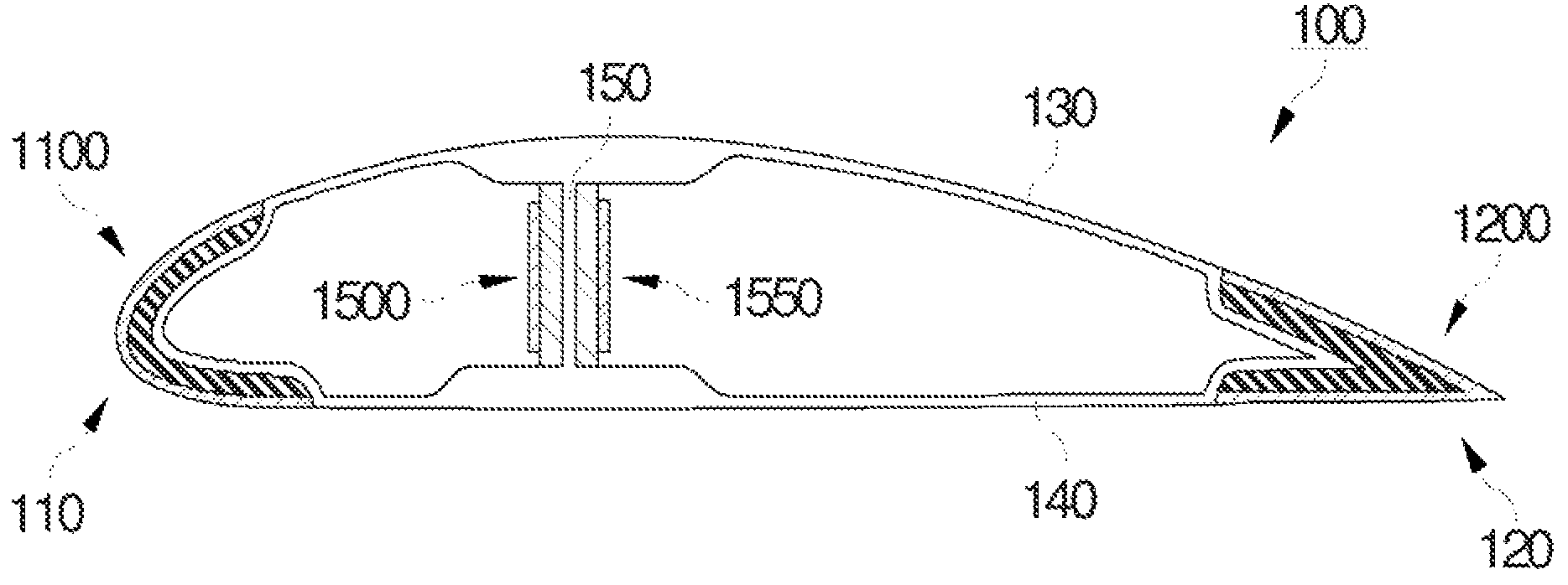
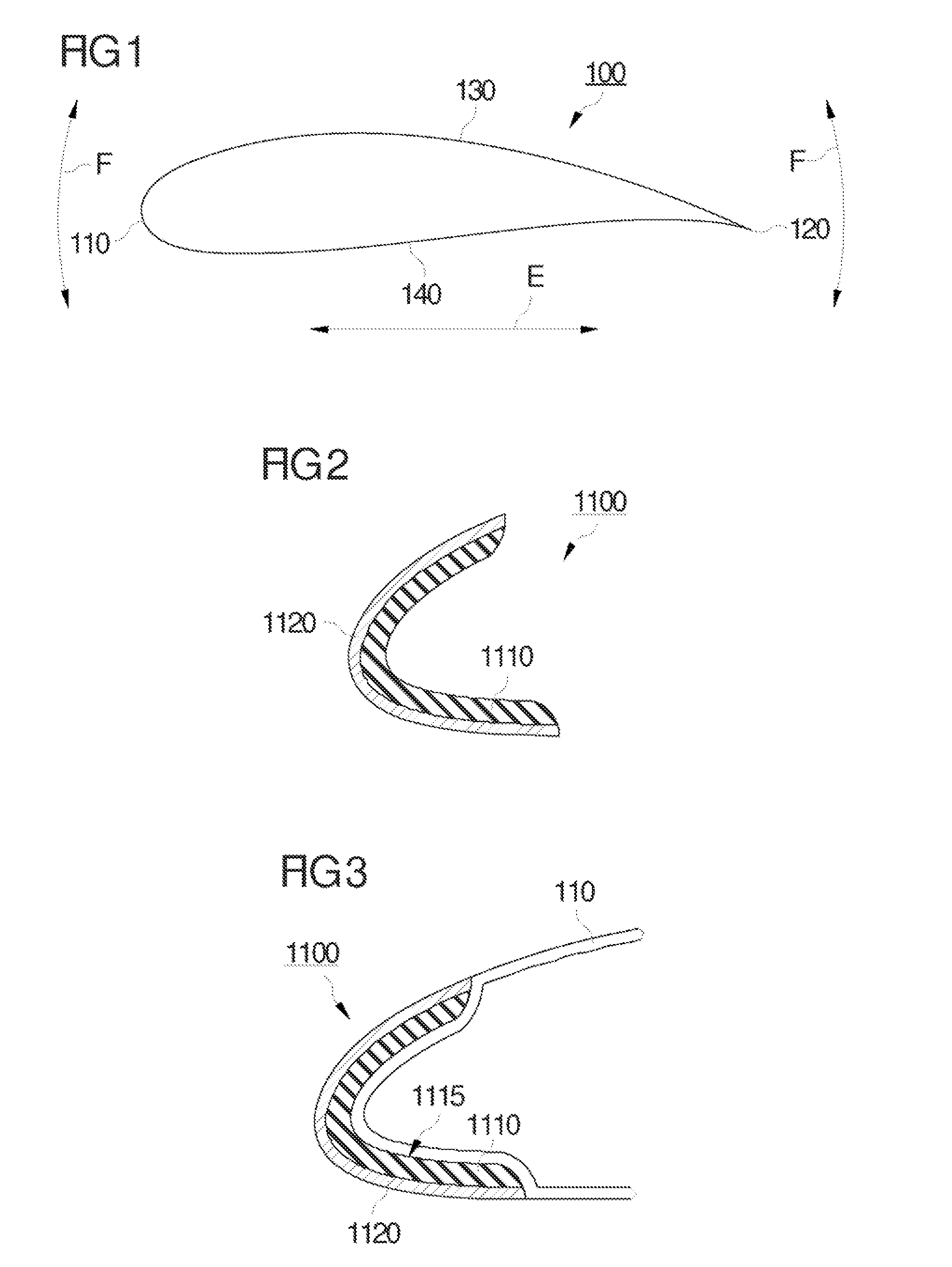
[0031]FIG. 1 shows a cross-sectional view of a wind turbine rotor blade. The cross-section is taken in a plane perpendicular to the longitudinal axis of the blade so that the airfoil or blade contour is shown. The body of the rotor blade 100 has a leading edge 110 and a trailing edge 120 which are connected by a suction side 130 and a pressure side 140. Typically, the blade body 100 is made of fiber glass reinforced plastic (FGRP). Further details of the blade body configuratio...


PUM


Abstract

A damping element for a wind turbine rotor blade is provided, the damping element comprising a laminate material made of at least one viscoelastic layer and at least one stiff layer adhered to said viscoelastic layer, wherein the damping element is adapted to be attached to a body of the rotor blade so that the at least one viscoelastic layer is in contact with the body of the rotor blade.

Description

BACKGROUND OF THE INVENTION[0001]The present invention relates to a damping element for a wind turbine rotor blade, a wind turbine rotor blade including such a damping element and a wind turbine equipped with a wind turbine rotor blade having a damping element.[0002]Wind turbine rotor blades are used to extract kinetic energy from the wind and to convert this kinetic energy into rotational energy of a driving shaft. Typically, the driving shaft is connected to an electric generator for power generation but may also be used to drive a pump, a mill work or the like. In any case, the rotor blades are subject to high loads caused by short-term fluctuations of wind speed. In particular, wind gust loads affect the structural blade design and permanent wind turbulence provides a substantial contribution to material fatigue of the rotor blades.[0003]To withstand the above-described wind gust loads, wind turbine rotor blades are typically made from fiber-reinforced plastics with a polymer re...

Claims


Application Information

Patent Timeline
Patent Type & Authority Patents(United States)
IPC IPC(8): F03D11/00
CPCF03D1/0675F05B2260/96Y02E10/721Y02E10/72Y10S416/50
Inventor BONNET, LAURENT
Owner GENERAL ELECTRIC CO
Why Eureka
Try Eureka