Digital frequency detector and digital phase locked loop using the digital frequency detector

a technology of digital frequency detector and digital phase lock, which is applied in the direction of oscillation comparator circuit, automatic control, instruments, etc., can solve the problems of lowering the accuracy of digital pll, and problems not only in the digital pll but also in the frequency synthesizer, so as to improve the performance of a digital circuit and high precision

Inactive Publication Date: 2010-10-12
SAMSUNG ELECTRONICS CO LTD
View PDF7 Cites 33 Cited by
  • Summary
  • Abstract
  • Description
  • Claims
  • Application Information

AI Technical Summary

Benefits of technology

[0016]The present invention provides a digital frequency detector that can detect the frequency of a high frequency signal as a digital signal having a high precision to improve the performance of a digital circuit in designing a circuit, which had been designed in an analog domain, in a digital domain, and a digital PLL using the digital frequency detector.

Problems solved by technology

In implementing a digital PLL, the biggest problem is that the accuracy of the digital PLL is lowered in the case of converting the high frequency signal output from the VCO into a digital signal.
The problem occurs not only in the digital PLL but also in a frequency synthesizer and the like, designed in the digital domain.

Method used


Image

  • Digital frequency detector and digital phase locked loop using the digital frequency detector
  • Digital frequency detector and digital phase locked loop using the digital frequency detector
  • Digital frequency detector and digital phase locked loop using the digital frequency detector

Examples


Embodiment Construction

[0051]Certain exemplary embodiments of the present invention will now be described in greater detail with reference to the accompanying drawings.

[0052]In the following description, same drawing reference numerals are used for the same elements even in different drawings. The matters defined in the description, such as detailed construction and elements, are provided to assist in a comprehensive understanding of the invention. Thus, it is apparent that the exemplary embodiments of the present invention can be carried out without those specifically defined matters. Also, well-known functions or constructions are not described in detail since in order to prevent obscuring the invention with unnecessary detail.

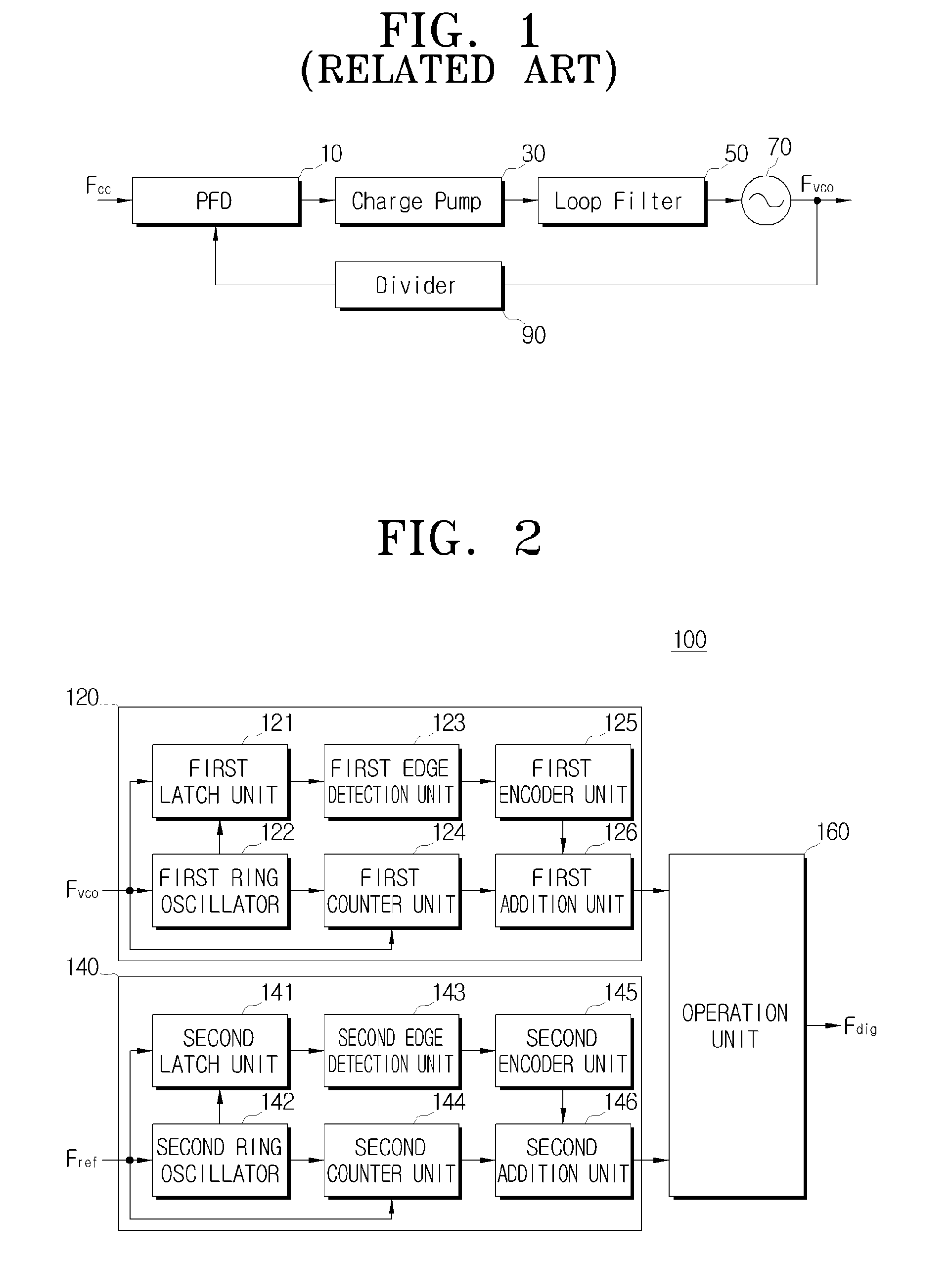
[0053]FIG. 2 is a block diagram schematically illustrating the construction of a digital frequency detector according to an exemplary embodiment of the present invention.

[0054]Referring to FIG. 2, the digital frequency detector 100 according to an exemplary embodiment of the prese...


PUM


Abstract

A digital frequency detector and a digital phase locked loop (PLL) are provided. The digital frequency detector includes a first conversion unit which outputs a first frequency as first frequency information of a digital type using a first ring oscillator that operates in a high-level period of the first frequency, a second conversion unit which outputs a second frequency as second frequency information of a digital type using a second ring oscillator that operates in a high-level period of the second frequency, and an operation unit which outputs a digital frequency for the first frequency by calculating a ratio of the first frequency information to the second frequency information.

Description

CROSS-REFERENCE TO RELATED APPLICATIONS[0001]This application claims priority from Korean Patent Application No. 10-2007-0062354, filed on Jun. 25, 2007 in the Korean Intellectual Property Office, the disclosure of which is incorporated herein by reference in its entirety.BACKGROUND OF THE INVENTION[0002]1. Field of the Invention[0003]Apparatuses consistent with the present invention relate to a digital frequency detector and a digital phase locked loop (PLL) using the digital frequency detector. More particularly, apparatuses consistent with the present invention relate to a digital frequency detector for use in a digital PLL or a frequency synthesizer, and a digital PLL using the digital frequency detector.[0004]2. Description of the Related Art[0005]Generally, a PLL is used to obtain an output signal having a fixed phase and frequency by sensing and controlling the change of the phase and frequency that may occur in peripheral environments.[0006]FIG. 1 is a block diagram schemati...

Claims


Application Information

Patent Timeline
Patent Type & Authority Patents(United States)
IPC IPC(8): G01R25/00H03D13/00
CPCH03D13/003H03L7/091H03L7/089
Inventor CHA, CHOONG-YULKIM, TAE-WOOKLEE, JAE-SUP
Owner SAMSUNG ELECTRONICS CO LTD
Why Eureka
Try Eureka