Liquid crystal aligning device and alignment method thereof

a technology of aligning device and liquid crystal, which is applied in the manufacture of electrode systems, electric discharge tubes/lamps, instruments, etc., can solve the problems of display failure, difficult and time-consuming, and difficulty in seeing images on the display

Inactive Publication Date: 2010-10-12
CHI MEI COMM SYST INC
View PDF10 Cites 4 Cited by
  • Summary
  • Abstract
  • Description
  • Claims
  • Application Information

AI Technical Summary

Benefits of technology

[0004]Liquid crystal display (LCD) devices have come into widespread use in recent years because of their advantages such as the ability to allow production of thinner devices and offer lower power consumption than display devices that utilize cathode ray tubes. Generally, LCD devices are divided into two types: a transmissive type and a reflective type. The transmissive LCD device utilizes light from a so-called backlight to provide a display. However, when the transmissive LCD device is used outdoors sunlight may make it difficult to see images on the display. The reflective LCD device, however, reflects outside light and utilizes the light to provide a display. In this way, the reflective LCD device is capable of providing a satisfactory display outdoors, but not in darker environments. Hence, a so-called transflective LCD device having the functions of both the transmissive and reflective LCD devices is receiving attention.

Problems solved by technology

However, when the transmissive LCD device is used outdoors sunlight may make it difficult to see images on the display.
However, when liquid crystals are aligned by rubbing, dust is produced or static electricity generated and both may cause a display failure.
In addition, for a transmissive area and a reflective area of the liquid crystal device, in order to achieve different predetermined phase retardation, two different curing voltages and multiple exposures should be applied to the liquid crystal device, which is difficult and time consuming.

Method used


Image

  • Liquid crystal aligning device and alignment method thereof
  • Liquid crystal aligning device and alignment method thereof
  • Liquid crystal aligning device and alignment method thereof

Examples


Embodiment Construction

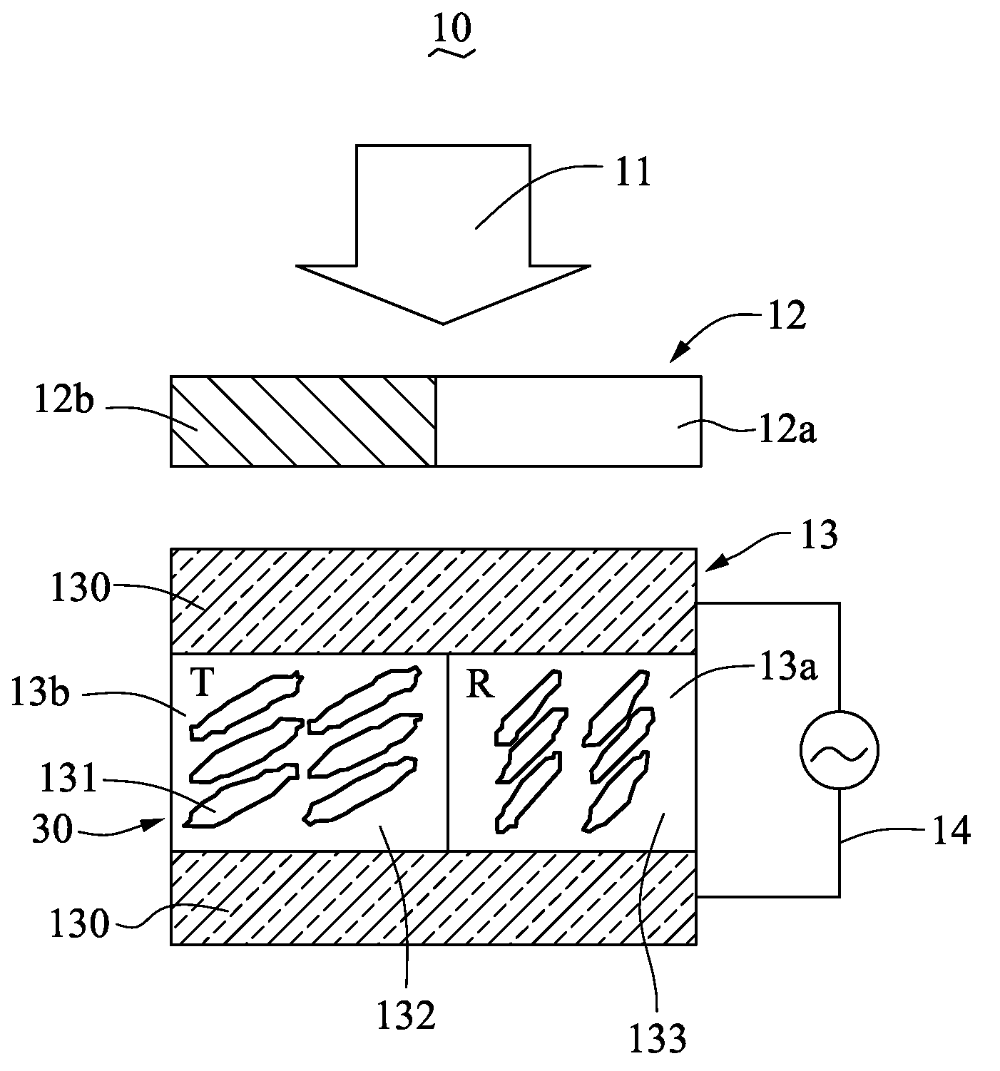
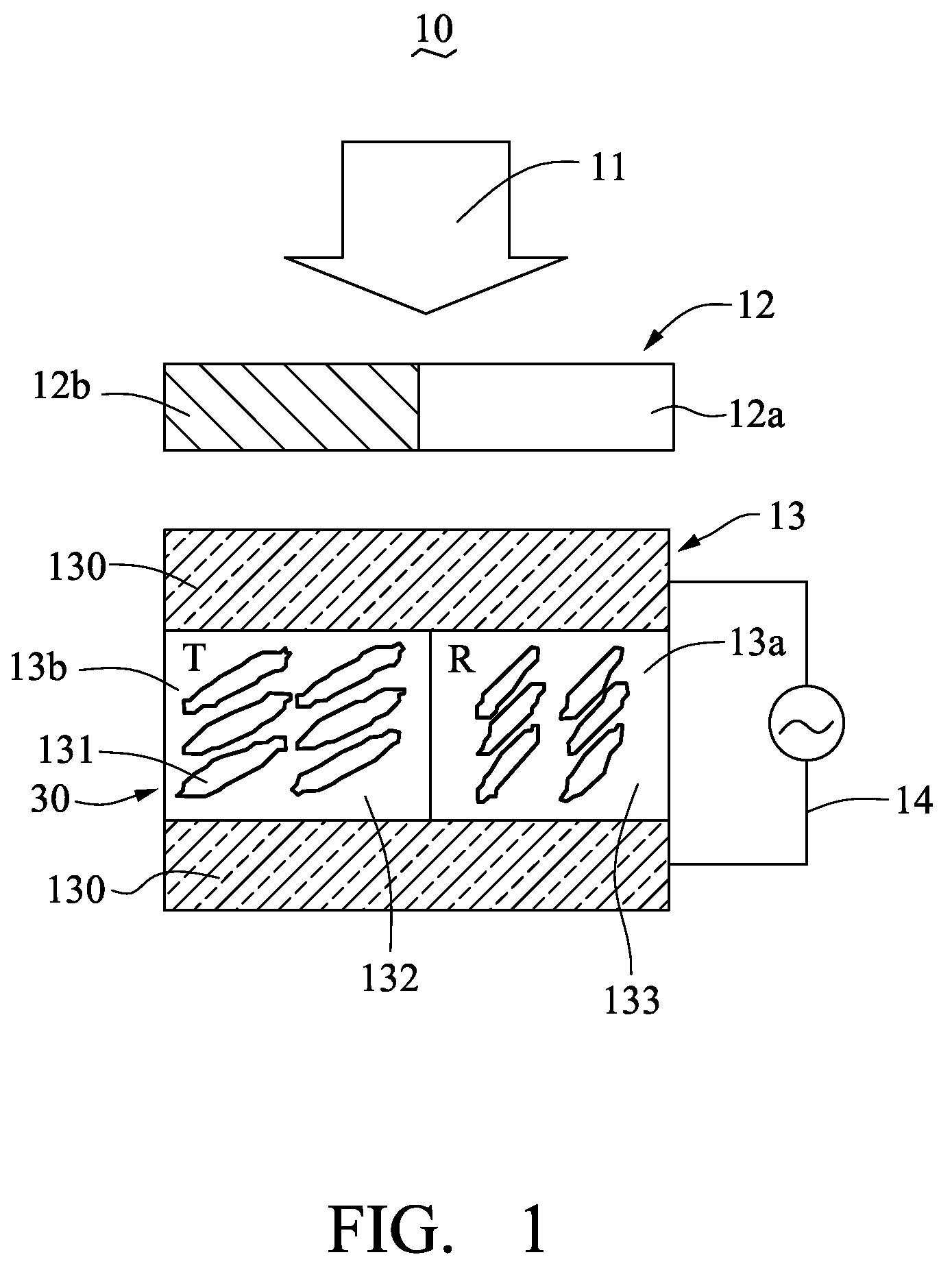
[0015]FIG. 1 schematically shows a liquid crystal aligning device 10 including a UV light source 11, a mask 12, a plurality of liquid crystal cells 13 configured (structured and arranged) for forming an LCD, and a drive circuit 14.

[0016]Each liquid crystal cell 13 includes a pair of substrates 130 and a liquid crystal layer 30 between the substrates 130. The liquid crystal layer 30 includes a mixture of a UV polyimide solution (not shown) and liquid crystal molecules 131 having positive dielectric anisotropy. Each liquid crystal cell 13, i.e., a picture element (a minimum display unit) includes a reflective area 13a (shown as “R”) and a transmissive area 13b (shown as “T”). Three liquid crystal cells 13, representing red (R), green (G), and blue (B), respectively form a single “pixel”.

[0017]For illustration purposes only, FIG. 1 shows the volume of the reflective area 13a equal the volume of the transmissive area 13b. However, the reflectivity of the liquid crystal aligning device 1...


PUM

PropertyMeasurementUnit
volume ratioaaaaaaaaaa
wavelengthaaaaaaaaaa
pre-tilt angleaaaaaaaaaa

Abstract

A liquid crystal aligning device (10) includes a UV light source (11), a plurality of liquid crystal cells (13), a mask (12), and a drive circuit (14) is described. The mask (12) is positioned between the liquid crystal cells, containing a mixture of a UV polyimide solution and liquid crystal molecules (131), and the UV light source. The drive circuit applies a voltage to the liquid crystal cells. The liquid crystal cells include a reflective area (13a) and a transmissive area (13b), and after exposing the liquid crystal cells to the UV light source and the voltage from the drive circuit, a pretilt angle of the liquid crystal molecules in the reflective area is larger than that in the transmissive area. Further, an alignment method for liquid crystal cells is also described.

Description

BACKGROUND[0001]1. Field of the Invention[0002]The present invention relates to liquid crystal aligning devices and alignment methods and, particularly to a liquid crystal aligning device used for alignment of transflective liquid crystal displays and an alignment method thereof.[0003]2. Discussion of the Related Art[0004]Liquid crystal display (LCD) devices have come into widespread use in recent years because of their advantages such as the ability to allow production of thinner devices and offer lower power consumption than display devices that utilize cathode ray tubes. Generally, LCD devices are divided into two types: a transmissive type and a reflective type. The transmissive LCD device utilizes light from a so-called backlight to provide a display. However, when the transmissive LCD device is used outdoors sunlight may make it difficult to see images on the display. The reflective LCD device, however, reflects outside light and utilizes the light to provide a display. In thi...

Claims


Application Information

Patent Timeline
Patent Type & Authority Patents(United States)
IPC IPC(8): G02F1/1339G02F1/1337
CPCG02F1/133788G02F1/133555G02F2001/133761G02F1/133761
Inventor CHU, KUEI-LIN
Owner CHI MEI COMM SYST INC
Why Eureka
Try Eureka