Microfluidic reaction apparatus for high throughput screening
a technology of microfluidic reaction and high throughput, which is applied in the direction of flow mixer, diaphragm, electrolysis, etc., can solve the problems of difficult filling and reading the plates, and the equipment maker makes little effort to develop systems that are cross-compatible with the systems of other manufacturers
- Summary
- Abstract
- Description
- Claims
- Application Information
AI Technical Summary
Benefits of technology
Problems solved by technology
Method used
Image
Examples
example 1
Fabrication and Operation of Carry-On Reaction Cells
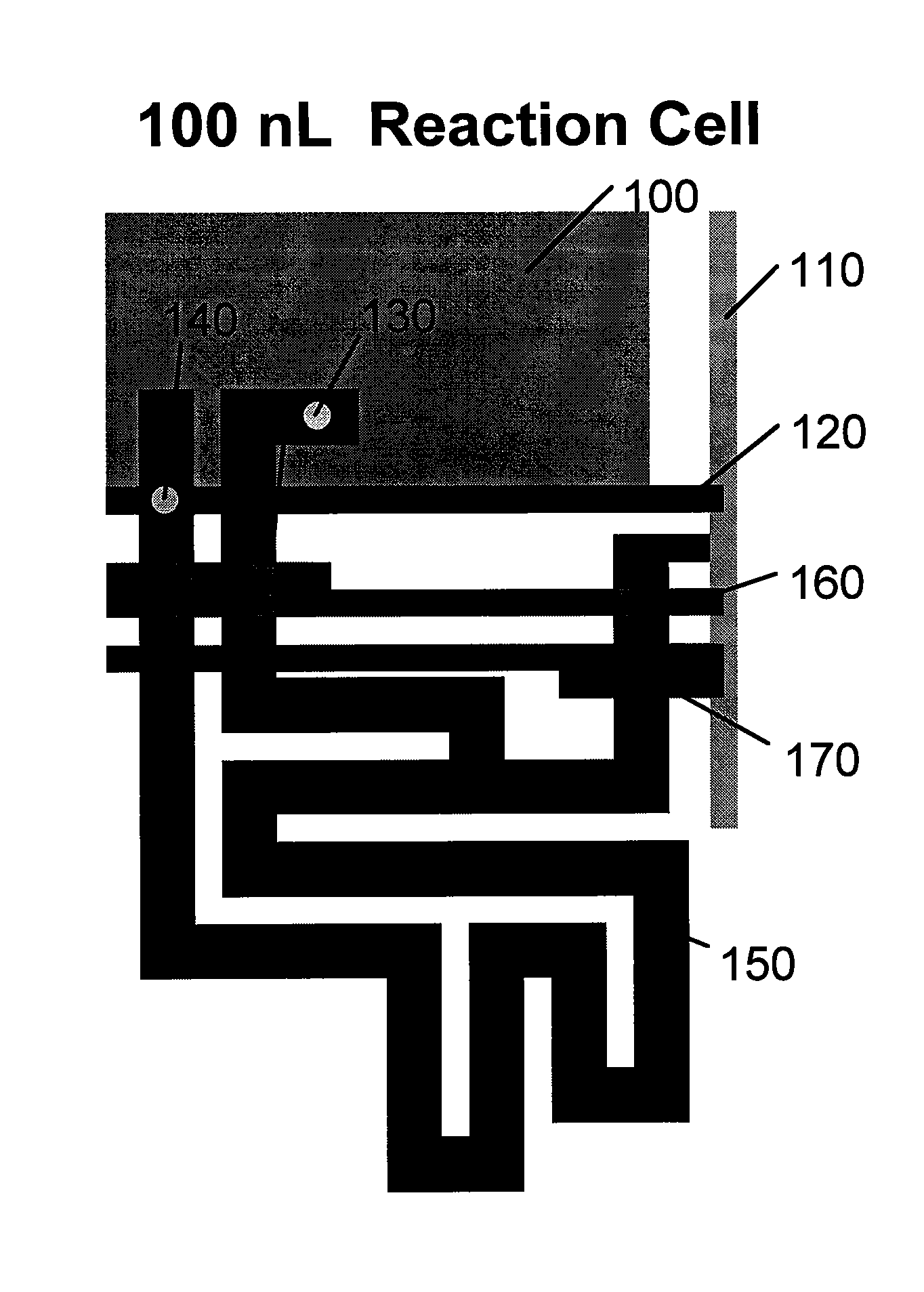
[0137]Reaction cells are fabricated in 100 nL (FIG. 9A), 10 nL (FIG. 9B), and 1.5 nL (FIG. 9C) volumes by multilayer soft lithography. A reaction chamber 100 is prepared on a first spin layer of varying thicknesses. For a 100 nL reaction chamber, a 100 μm recess is patterned with SU8 photoresist and a first polydimethylsiloxane (PDMS) elastomeric layer is prepared by spin coating the resist pattern to define a 100 nL reaction chamber (100) with an open side and a closed side. Once the first layer is cured, a via (130) is laser punched through the closed side of the reaction chamber. A second elastomeric layer is prepared by spin coating a resist pattern to define a 10 μm rounded reagent slug channel (150) in fluidic communication with a 30 μm rounded reagent input flow channel (110). The channels are formed as recesses in the second layer. The reagent input flow channel is formed as a bus channel to connect with additional reagent ...
example 2
Fabrication of a Matrix Reaction Array
[0139]A 32×32 elastomeric microfluidic matrix reaction array with slug mixing was constructed and mixing efficiency was compared to a conventional 32×32 elastomeric microfluidic matrix reaction array constructed with a sample / reaction chamber adjacent to a reagent chamber and separated by an interface valve.
[0140]The matrix reaction array was constructed with each reaction cell comprising a central 50 nL reaction chamber (400) and a 5 nL slug channel (250) as shown in FIG. 10. The unit reaction cell of FIG. 2 was repeated to prepare a 32×32 matrix fluidic circuit. Using multilayer soft lithography, a first pour layer was patterned with SU8 photoresist to form a mold and then cast with PDMS. The features of the pour layer included a 350 μm tall reaction chamber and a 30 μm tall slug channel. The other, feature, a connecting channel (300) was constructed with a height of 10 μm. A second spin layer was prepared with 15 μm tall features for sample i...
example 3
Demonstration of the Filling and Mixing of a 32×32 Matrix Reaction Array
[0142]Operation of the matrix reaction array was performed by the following steps. Control channel 1 (260) was pressurized to close the valves that fluidically isolate the ends of the slug channel (FIG. 12A). A yellow food dye was introduced under pressure through the connecting channels (300) and the slug channels were blind-filled (FIG. 12B). This step simulates the filling of the slug channel with reagent. Following the filling of the slug channels, control channel 2 (270) is pressurized to actuate the valves that close off the connecting channels (300) and thereby isolate the individual slug channels from the other slug channels in the columns. Although all columns in the reaction array and, accordingly, all slug channels, are filled with the same yellow food dye in this example, there is no interconnection between the connecting channels and the slug channels of the individual columns. Following the blind f...
PUM
| Property | Measurement | Unit |
|---|---|---|
| area | aaaaa | aaaaa |
| area | aaaaa | aaaaa |
| area | aaaaa | aaaaa |
Abstract
Description
Claims
Application Information
 - R&D
- Intellectual Property
- Life Sciences
- Materials
- Tech Scout
- Unparalleled Data Quality
- Higher Quality Content
- 60% Fewer Hallucinations
Browse by: Latest US Patents, China's latest patents, Technical Efficacy Thesaurus, Application Domain, Technology Topic, Popular Technical Reports.
© 2025 PatSnap. All rights reserved.Legal|Privacy policy|Modern Slavery Act Transparency Statement|Sitemap|About US| Contact US: help@patsnap.com


