Neutral atom trapping device

a technology of neutral atoms and trapping devices, which is applied in the direction of irradiation devices, nuclear engineering, masers, etc., can solve the problems of insufficient capture of atoms, inability to completely compensate magnetic distortion, and inability to compose magnetic traps on this magnetic field, so as to achieve greater capacity, less electric current, and capture neutral atoms more effectively

Inactive Publication Date: 2010-10-19
NAT INST OF INFORMATION & COMM TECH
View PDF6 Cites 19 Cited by
  • Summary
  • Abstract
  • Description
  • Claims
  • Application Information

AI Technical Summary

Benefits of technology

[0020]It is an object of the present invention to provide magneto-optical traps and / or magnetic traps which can capture neutral atoms more effectively with lesser electric current than the prior art.
[0040]According to the present invention, magneto-optical traps and / or magnetic traps which can further miniaturize the whole device than the prior art can be provided.

Problems solved by technology

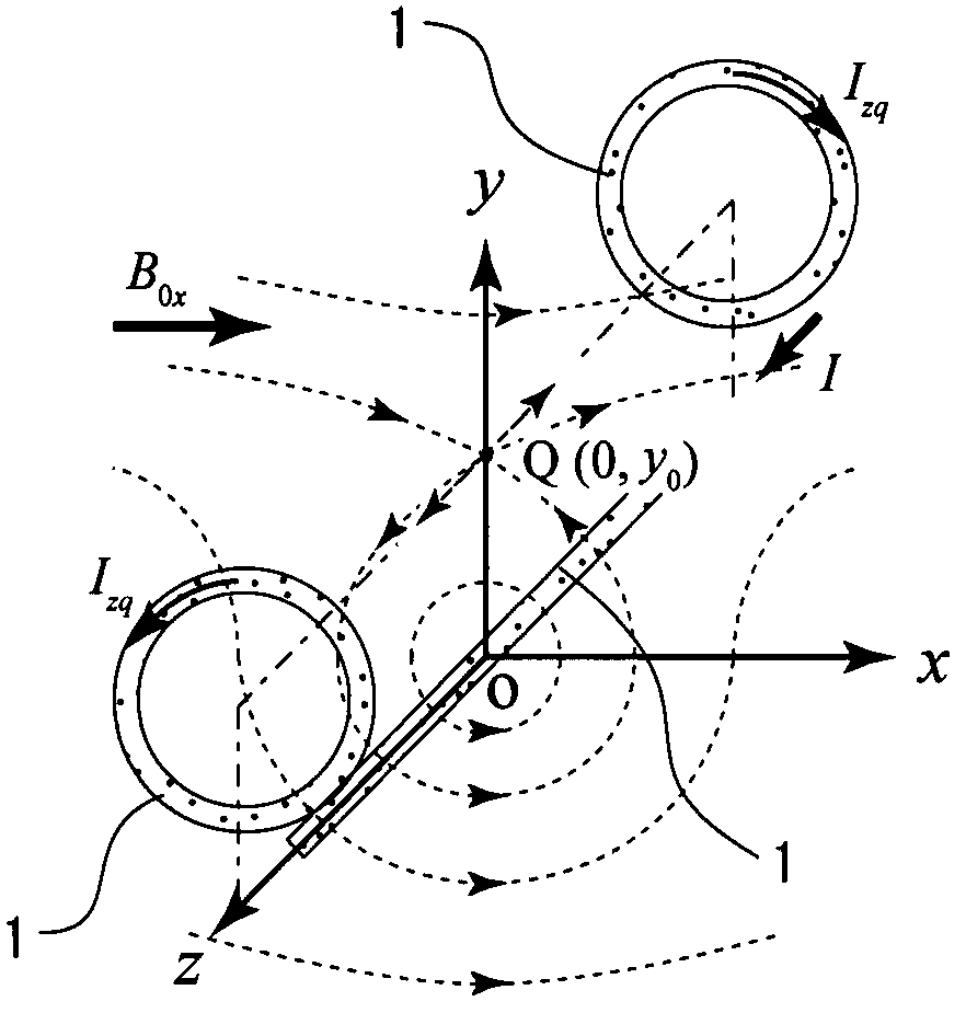
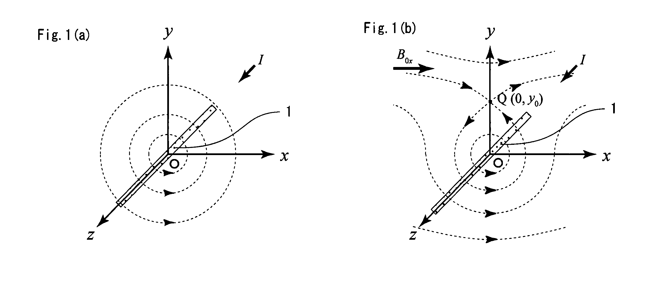
However, a magneto-optical trap cannot be composed on this magnetic field since the z component of the magnetic field faces the positive (+) direction of the z-axis everywhere in the magnetic field.
If a magneto-optical trap is composed by using such a magnetic field, there is a problem that the effective capacity in the space where atoms drifting in the vacuum are captured becomes limited, so that sufficient numbers of atoms cannot be captured.
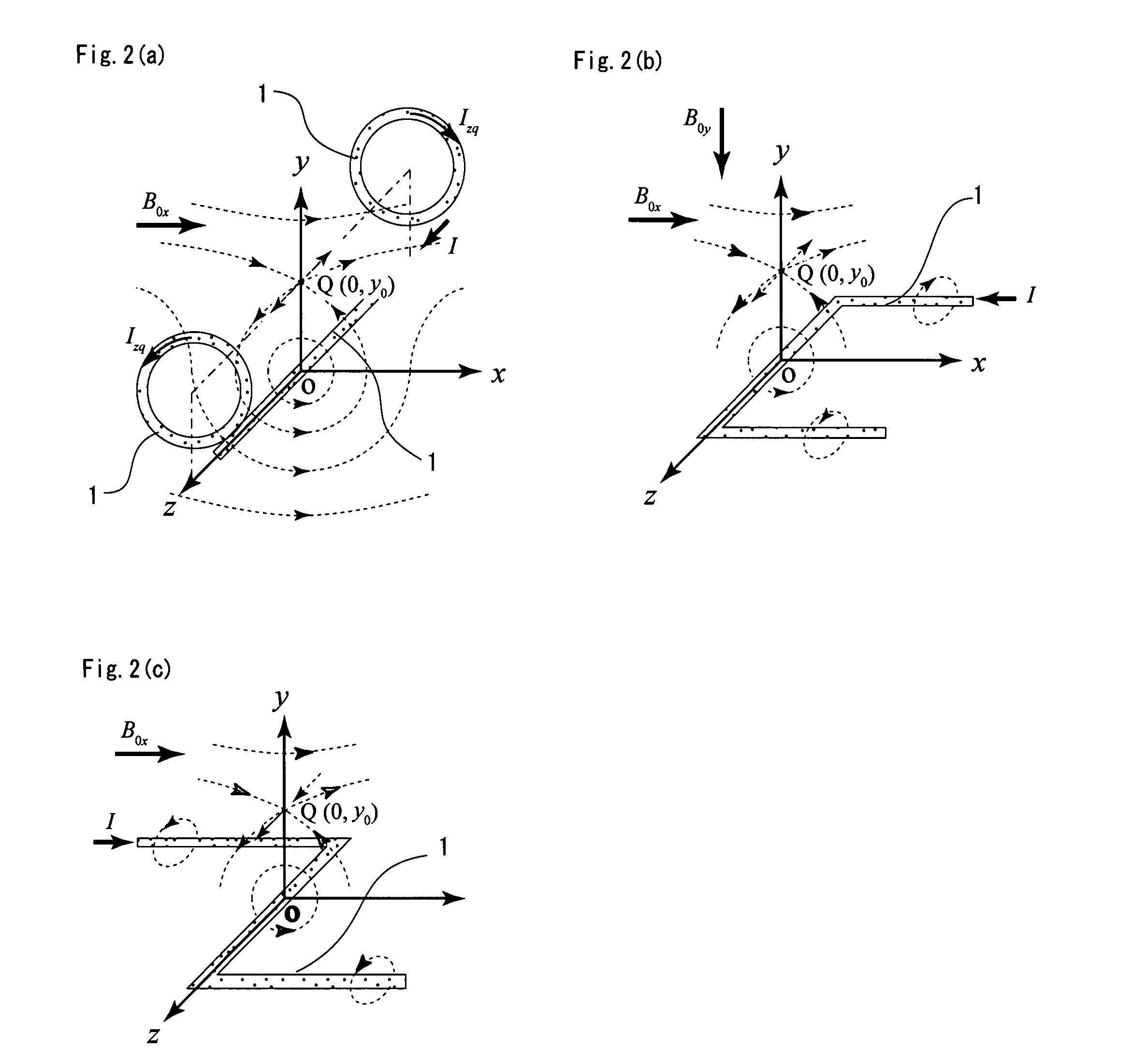
However, even when such a plate conductor is used, a magnetic distortion cannot be completely compensated, and an extra electric current has to be flowed through in proportion to the widened portion of the conductor.
Since a magneto-optical trap and a magnetic trap are placed in an ultrahigh vacuum device, there may be a situation where gas is emitted from a surface of a conductor when the amount of heat generated is increased, which is not desirable.
Furthermore, since the two Ioffe bars extending in the x-direction from both ends of the central conductor are relatively long, an unnecessarily large z-directed bias magnetic field is generated, so that in order to compensate said bias magnetic field, a large z-directed bias magnetic field has to be further added from outside.
Accordingly, there is a problem that the whole device cannot be miniaturized even when a magnetic trap with a Z-shaped conductor show in FIG. 2(c) is used.

Method used


Image

  • Neutral atom trapping device
  • Neutral atom trapping device
  • Neutral atom trapping device

Examples


example 1

Analasys for Equal Magnetic Potentials Wherein Sub-Currents are Placed in Parallel to Main Current

[0089]FIGS. 11(a) and 11(b) show calculation results comparing a shape of two-dimensional magnetic field generated by the main current I1 alone, with that generated by canceling a hexapole magnetic field using the main electric current I1 together with the sub-current I2. FIGS. 11(a) and 11(b) are graphs showing the calculation result comparing the two-dimensional magnetic field generated by the main current I1 alone, with that generated by the cancellation process of the hexapole magnetic field when both the main current I1 and the sub-current I2 are used. FIG. 11(a) shows a magnetic field generated by the main current I1 alone, FIG. 11(b) shows the behavior of the magnetic field structure in two dimensions generated by completely canceling the hexapole magnetic field using the main current I1 together with the sub-current I2. FIGS. 11(a) and 11(b) depict equal magnetic potential lines...


PUM


Abstract

A neutral atom trapping device with a multipole-magnetic field-generating electrode is provided with a main current electrode through which main current flows, and a pair of sub-current electrodes through which sub-current flows, and which is located in parallel to and both sides of said main current electrode; a neutral atom trapping device with an S-shaped multipole-magnetic field-generating electrode.

Description

BACKGROUND OF THE INVENTION[0001]1. Field of the Invention[0002]The present invention relates to a neutral atom trapping device, and in particular to a neutral atom trapping device which specializes a multipole-magnetic field-generating electrode in a magneto-optical trap or / and a magnetic trap to enhance a magnetic quadrupole component while attenuating a magnetic hexapole component in the region where neutral atoms are captured, so that neutral atoms can be effectively captured, and which reduces an applied current and / or an external magnetic field by generating the magnetic field, thereby enabling miniaturization of the whole device.[0003]2. Description of the Related Art[0004]Magneto-optical trap [MOT] is a publicly-known technology in the field of atom optics. By using a magneto-optical trap, neutral atoms can be captured by irradiating laser beams of well-adjusted oscillating frequency along the axis of symmetry of the magnetic field lines in a quadrupole magnetic field. Since...

Claims


Application Information

Patent Timeline
Patent Type & Authority Patents(United States)
IPC IPC(8): G21K5/00H01S4/00
CPCG21K1/006H05H3/04
Inventor HYODO, MASAHARU
Owner NAT INST OF INFORMATION & COMM TECH
Why Eureka
Try Eureka