
Floating wind turbine installation

a installation platforms, which is applied in the direction of special-purpose vessels, machine/engines, vessel construction, etc., can solve the problems of limited current technology of floating wind turbines, high cost, and technical problems, and achieve satisfactory technical solutions and low cost

Active Publication Date: 2010-10-26
HYWIND AS
View PDF13 Cites 15 Cited by
  • Summary
  • Abstract
  • Description
  • Claims
  • Application Information

AI Technical Summary

Benefits of technology

[0008]The present invention represents a solution that makes it possible to achieve a combination of material use, geometric and dimensional design and structural solutions that produces satisfactory technical solutions and sufficiently low costs to make the concept financially attractive.
[0010]The large displacement and high strength required for deeply immersed structures can be achieved, in accordance with the present invention, in a simple, cost-effective manner by using concrete in a cylindrical underwater part. Concrete is a cheap material. By systematizing and organizing the construction methods for series production, the labor costs will be very low.
[0011]Another important precondition for low overall costs is the need to avoid extensive work with expensive auxiliary vessels when the individual turbines are installed at sea. This is achieved in that the entire turbine can be towed out fully assembled and anchored with a simple anchor system.

Problems solved by technology

Current technology for wind turbines located at sea is limited to permanently installed towers at low depths, i.e., under approximately 30 m.
Permanent installations at depths over 30 m generally result in technical problems and high costs.
This has meant that, until now, sea depths of more than around 30 m have been regarded as technically and commercially unfavorable for the installation of wind turbines.
However, it is difficult to find solutions that are technically satisfactory and financially viable.

Method used


Image

  • Floating wind turbine installation
  • Floating wind turbine installation
  • Floating wind turbine installation

Examples


Embodiment Construction

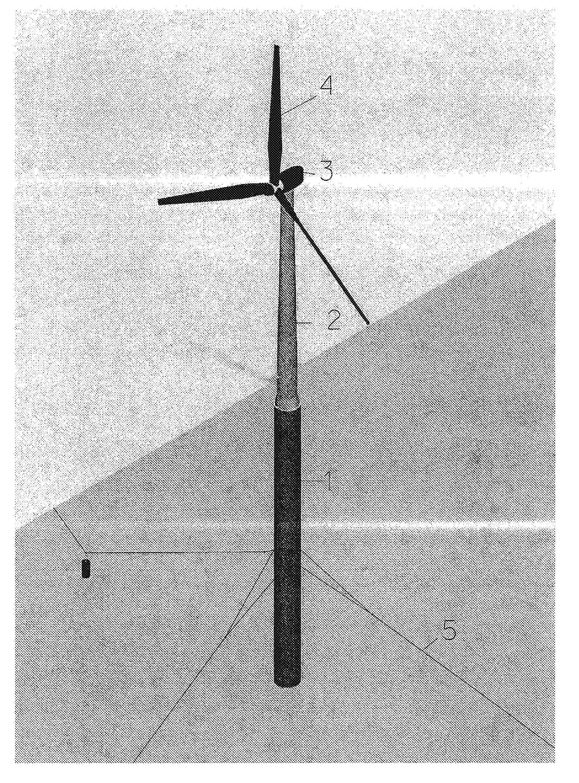
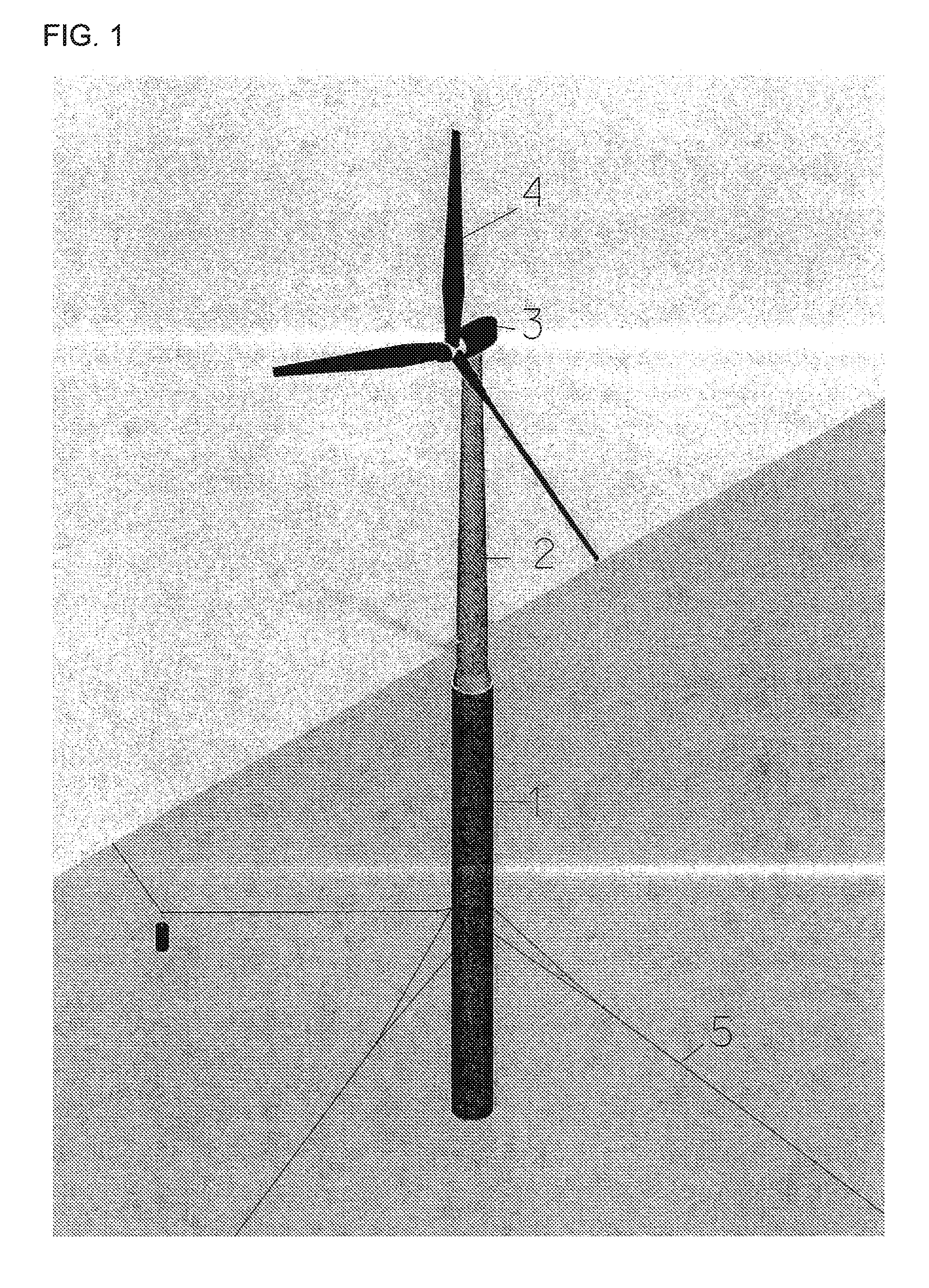
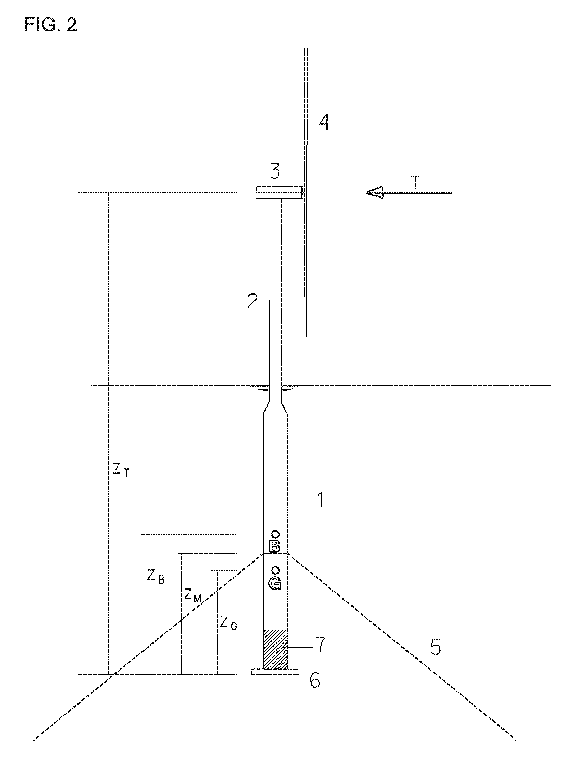
[0018]A floating wind turbine installation will primarily, as shown in FIG. 1 and FIG. 2, consist of an anchored floating foundation or buoyant body 1 that supports a high tower 2 with a wind turbine mounted on top of it. The wind turbine includes a generator housing 3 that encloses a power generation unit (not shown) and a rotor 4 arranged in connection with this unit. A major factor is that the floating foundation moves with the waves, which, in itself, is negative in relation to operation of the turbine and load on the tower. Another factor is that, on account of limited stability, the wind turbine installation will also heel when subject to wind force.

[0019]The main challenge in connection with the development of a floating wind turbine installation is, consequently, to minimize movement in waves and achieve optimum stability, while keeping costs low.

[0020]The cost is associated with the size of the installation. Consequently, an attempt will normally be made to achieve a concep...


PUM


Abstract

A method for coordinating a floating wind turbine installation. The wind turbine installation includes a buoyant body (1), a tower (2) arranged over the buoyant body, a generator (3) mounted on the tower which is rotatable in relation to the wind direction and fitted with a wind rotor (4), and an anchor line arrangement (5) connected to anchors or anchor points on the sea bed. Static heeling, φs<sub2>—< / sub2>max, at full wind load on the wind turbine is as low as possible, but preferably less than 8 degrees, and all eigenperiods for the installation are outside the waves' period range. The eigenperiod in pitch, T05 (roll, T04), is preferably less than 80% of the T03 eigenperiod in heave. Moreover, the ratio between T03 and T05 is not close to 0.5 or 1.

Description

BACKGROUND OF THE INVENTION[0001]1. Technical Field[0002]The present invention relates to a floating wind turbine installation and a method for coordinating the wind turbine installation's hydrostatic and hydrodynamic properties. The wind turbine installation comprises a buoyant body, a tower arranged over the buoyant body, a generator housing mounted on the tower which is rotatable in relation to the wind direction and fitted with a wind rotor, and an anchor line arrangement connected to anchors or anchor points on the sea bed.[0003]2. Description of the Related Art[0004]The development of floating, anchored wind turbines that can be used at great depths will strongly enhance access to areas for the expansion of wind energy at sea. Current technology for wind turbines located at sea is limited to permanently installed towers at low depths, i.e., under approximately 30 m.[0005]Permanent installations at depths over 30 m generally result in technical problems and high costs. This has...

Claims


Application Information

Patent Timeline
Patent Type & Authority Patents(United States)
IPC IPC(8): B63B35/44F03D1/00B63BB63B21/50
CPCB63B21/50F03D11/04E02B2017/0091F05B2240/93Y02E10/727F03D13/25B63B1/048B63B2001/044B63B2035/446Y02E10/72F03D1/00E02B2017/0095
Inventor SVEEN, DAGFINNNIELSEN, FINN GUNNARHANSON, TOR DAVID
Owner HYWIND AS
Learn More