Micro device for cell culture

a cell culture and micro-device technology, applied in biomass after-treatment, specific use bioreactors/fermenters, chemical/physical/physicochemical processes, etc., can solve the problems of inability to provide more sophisticated fluidic pattern or gradient formation of bio-molecules that imitate physiological environments in vivo

Inactive Publication Date: 2010-10-26
IND TECH RES INST
View PDF4 Cites 29 Cited by
  • Summary
  • Abstract
  • Description
  • Claims
  • Application Information

AI Technical Summary

Benefits of technology

[0007]The object of the present invention is to provide a micro device for culturing tissue-specific cells. The micro device of the present invention provides incubating conditions that imitate the physical environment in vivo. Further, the advantages of the present invention are to control the cytokines secretion by control of concentration gradient that mimic microenviroment of liver tissue, create opportunities for cell interaction between different types of cells, hepatocytes and non parenchymal cells, for example. In addition to function as a single culture device, the micro device can be further produced in batches format by disposable materials at low cost, to provide a personal medical device with great benefit.
[0014]The collecting well on the bottom plate can be directly connected with an outlet port in order to drain out the fluid from the collecting well. Alternatively, outlet ports can be defined in the top plate, orifice plate, and culture plate. While assembling the components, each outlet port and the collecting well on the bottom plate are connected so that back-flow of the fluid from the collecting well to the top plate and drain out from the outlet ports on the top plate is facilitated. As a result, the fluid in the collecting well on the bottom plate is circulated, and the objective of full utilization is achieved.
[0016]The utility of the orifice plate of the present invention depends on requirements, and there is no limitation for the structure of the orifice plate. A better result can be achieved when a plurality of orifices is formed, and each orifice connects with the injection ports and the buffer zone area which is formed when the top plate and the orifice plate are connected, and thus facilitates the fluid in the buffer zone area to diversify to culture plates.
[0022]This micro device performs even better when including a mechanical engineering control system and a biosensor. The mechanical engineering control system can manipulate the variety of fluids, the flow speed, the supply period, and the supply volume. Preferably, micro-patterning is formed inside each culture well. The structure of micro-patterning with at least one recess can be formed with bio-compatible materials by photosensitive procedures. Or, a pattern with at least one recess can be constructed in the culture wells by bio-compatible materials or bio-matrix, to control the growth and arrangements of cells.
[0023]The orifice plate of the invention decreases the probability of concentration variation and shear force occurring around the inlet port while the fluid flows into an culture well. The cooperation of orifices on the orifice plate and a hexagon-shape culture well achieves the best flow field effect, e.g. the shear force occurs more evenly when fluid flows from the six comers of the hexagon toward the center. Furthermore, the concentration gradient is formed within the cell culture wells by controlling the strength of inputting the fluid. The phenomenon reflects the concentration difference when a cell grows. For example, the concentration gradient of metabolism activity is different from central vein to portal vein of liver cells. The micro device for cell culture of the present invention can imitate the cell growing activity in physical environment in vitro.
[0025]By the fluid control system of this invention, different biomoleculars and drug delivery unit can be connected and automatically controlled to initiate or stop bio signal transmission at a sandwiched time interval. Moreover, a biosensor can also be connected to conduct feedback control on the returned signal. The biological systems can imitate how it transmits the growing factor to control cell behavior, and the long-term cultured cells can be in a more dynamic and varying environment. Therefore, the restraints or changes of the related metabolism system caused by growth factor concentrations degradation or unmorally high are avoided.

Problems solved by technology

Limitation of conventional static culture includes lack of mass transformation system of bimolecular and appropriate micro-architecture.
As for single-direction laminar flow, which unable to provide more sophisticated fluidic pattern or gradient formation of bio-molecules that imitate physiological environment in vivo.

Method used


Image

  • Micro device for cell culture
  • Micro device for cell culture
  • Micro device for cell culture

Examples


example 1

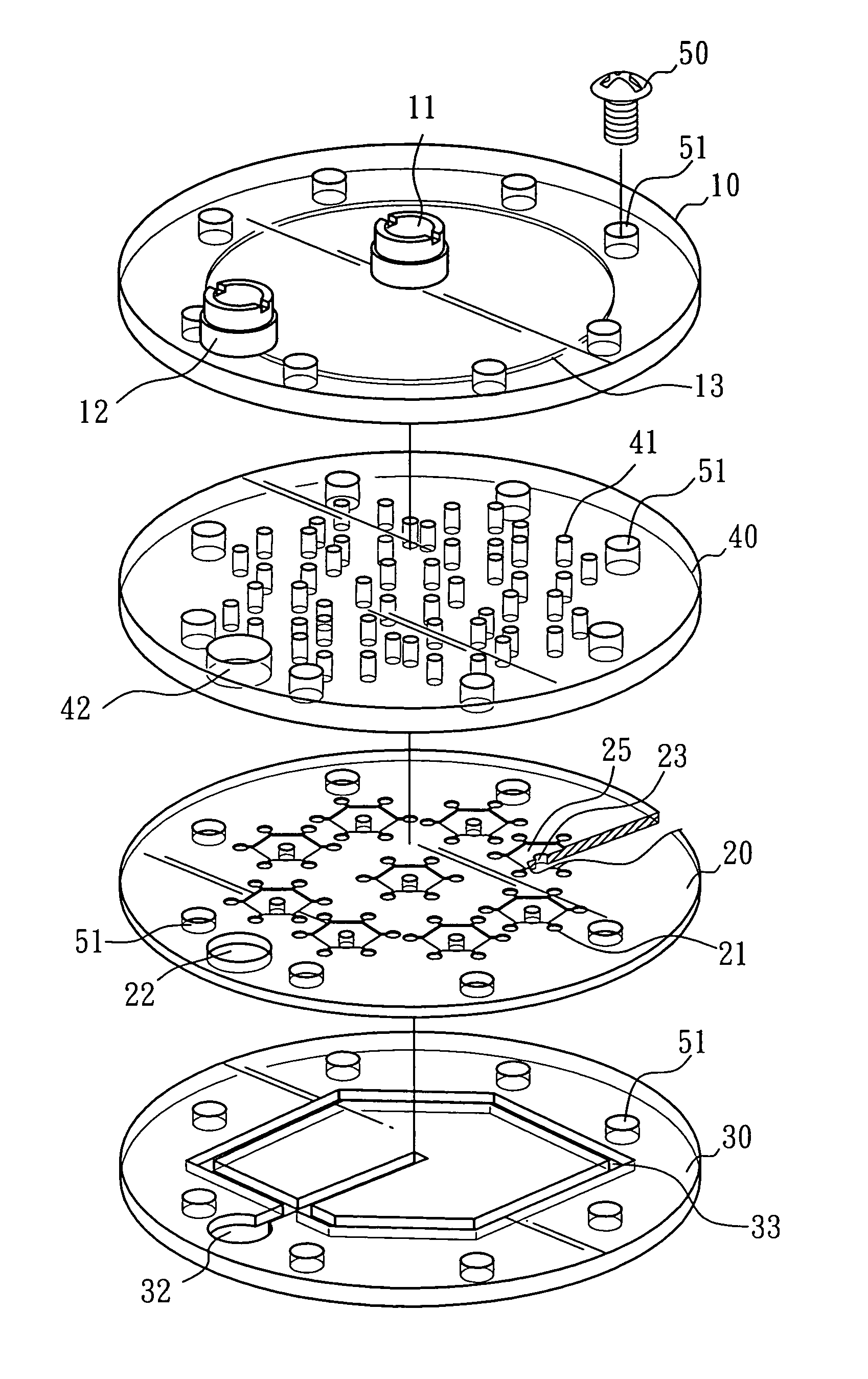
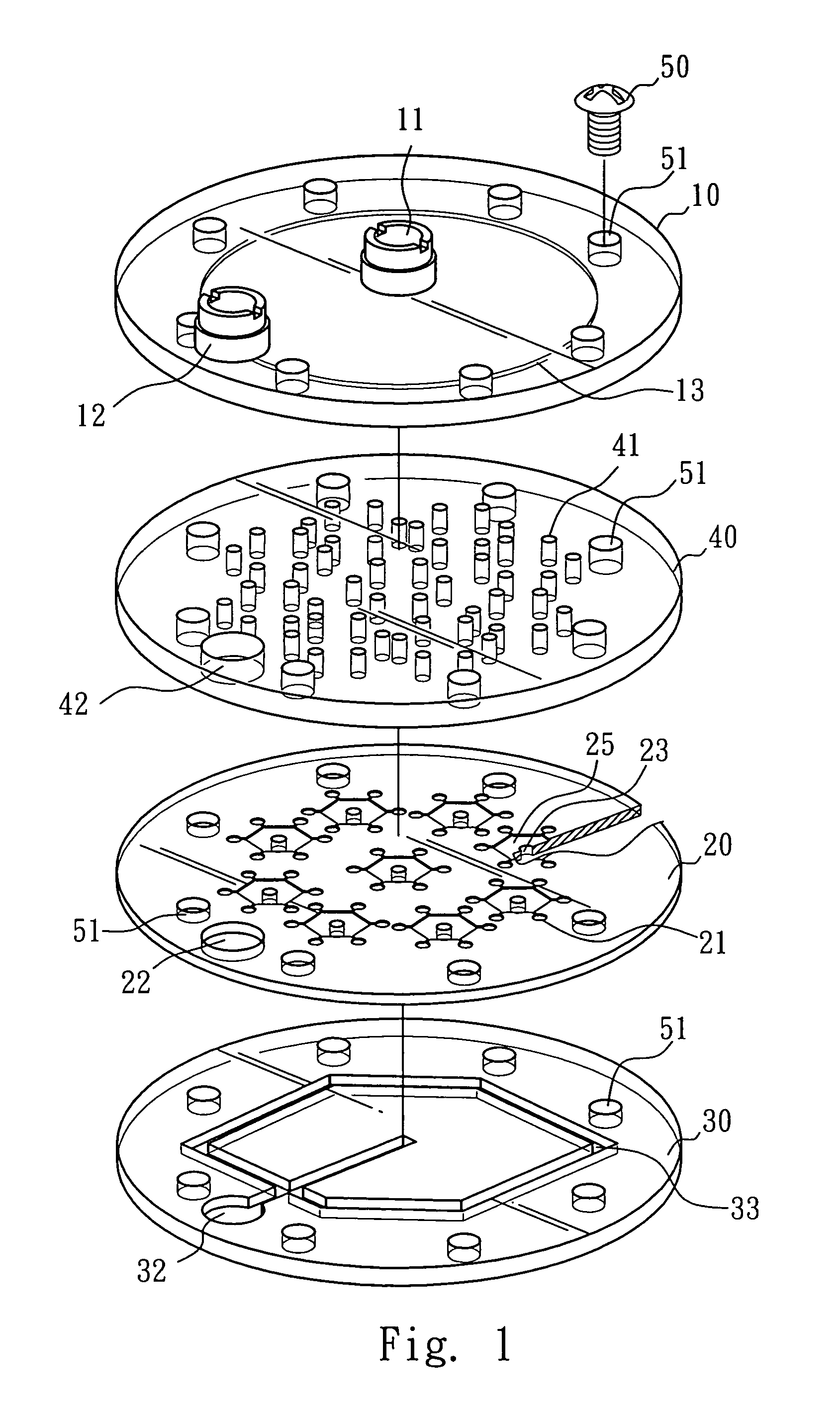
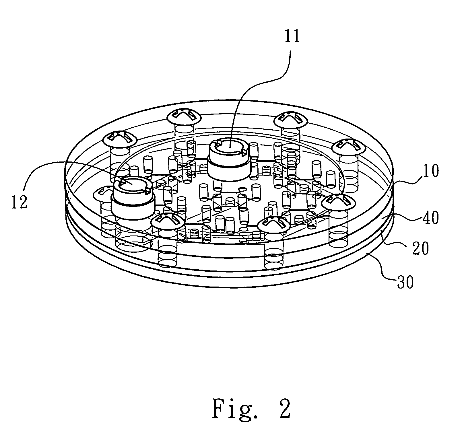
[0043]FIG. 1 is a detailed diagram of the micro device for cell culture. Four components are included which are: a top plate 10, a orifice plate 40, a culture plate 20, and a bottom plate 30. Each component has a plurality of screw holes 51 in which screws 50 are used to connect each component. In this example, eight screw holes 51 are formed on each component, to tightly connect with four components by screws 50. Therefore, cells cultured in the micro device can be prevented from being contaminated through external contacts during the culturing process.

[0044]An inlet port 11, an outlet port 12, and a buffer zone 13 are formed on the surface of the top plate 10. The buffer zone 13 is formed on the surface of the top plate 10 corresponding to the orifice plate 40. When the top plate 10 and the orifice plate 40 are assembled, the buffer zone 13 is formed and provides a temporary reserve for the fluid from inlet port 11 on the top plate 10.

[0045]A plurality of orifices 41 is formed on ...

example 2

[0052]The other structure of this device is as shown as in FIG. 3A. The buffer zone 13 formed on the top plate 10 can be formed on orifice plate 40 corresponding to a surface of top plate 10 instead, while the buffer zone 13 can also be formed when the top plate 10 and the orifice plate 40 are assembled.

example 3

[0053]As shown in FIG. 3B, the flow channel 33 and the collecting well 32 originally formed on the bottom plate 30 can also be formed on the culture plate 20 on a surface facing the bottom plate 30. The flow channel 33 and the collecting well 32 can thus be formed between the culture plate 20 and the bottom plate 30 when the micro device has been assembled.


PUM

PropertyMeasurementUnit
pressureaaaaaaaaaa
circle-shapeaaaaaaaaaa
shapeaaaaaaaaaa

Abstract

A micro device for cell culture is disclosed, which cooperates with a fluid and includes: a top plate having an inlet port; a orifice plate having a plurality of orifices; a culture plate having a plurality of culture wells and a plurality of injection ports; and a bottom plate having at least one collecting well and at least one collecting flow channel, wherein, the culture plate is placed between the orifice plate and the bottom plate. The collecting flow channel connects to all regulating orifices in the culture wells and guides the fluid from the culture wells, then receives the fluid in the collecting well. The fluid flows into the orifice plate from the inlet port of the top plate, and then diversifies into the culture plate, then arrives at each culture well by way of the injection ports, and finally collects in the collecting well of the bottom plate.

Description

BACKGROUND OF THE INVENTION[0001]1. Field of the Invention[0002]The present invention relates to a micro device for cell culture and, more particularly, to a micro device combining control systems that provide gradient formation of bio-molecules which imitates the physical tissue environment in vivo while culturing cells in vitro.[0003]2. Description of Related Art[0004]Cell culture techniques are basic in vitro tools used for studying varies biological or biomedical phenomena. During early stage of drug development, for example, cell culture techniques are frequently used to predict the metabolism and toxicology of drug candidates, or xenobiotics, instead of animal model experiments. The advantage of cell culture model is convenient and can used for speeding up the screening process.[0005]Generally, current cell culture methods can be classified into several groups: (1) conventional culture without fluidic environments, (2) fluidic culture with single-direction laminar flow. (3) ce...

Claims


Application Information

Patent Timeline
Patent Type & Authority Patents(United States)
IPC IPC(8): C12M3/00
CPCC12M23/12C12M23/16C12M23/58C12M41/40
Inventor WENG, YU-SHISHIH, MING-CHENGGAU, RUNG-JIUN
Owner IND TECH RES INST
Why Eureka
Try Eureka