Cascode amplifier and differential cascode voltage-controlled oscillator using the same

a voltage-controlled oscillator and amplifier technology, applied in the field ofdifferential, can solve the problems of degrading phase noise characteristics of the controlled oscillator, and achieve the effect of reducing phase nois

Inactive Publication Date: 2010-10-26
ELECTRONICS & TELECOMM RES INST
View PDF8 Cites 23 Cited by
  • Summary
  • Abstract
  • Description
  • Claims
  • Application Information

AI Technical Summary

Benefits of technology

[0014]Therefore, an object of the present invention is to provide a cascode amplifier with negative conductance and a differential cascode voltage-controlled oscillator using the cascode amplifier, which can reduce a phase noise by the use of a quality factor enhancement technique.
[0015]Another object of the present invention is to provide a cascode amplifier and a differential cascode voltage-controlled oscillator using the cascode amplifier, which can mitigate a ground-caused noise effect by the use of a cascode connection technique without the use of a current source so as to reduce influence on a noise generated in the current source.

Problems solved by technology

However, the related art voltage-controlled oscillator has a disadvantage that the phase noise characteristics thereof degrade because a noise component generated in the current source I1 exerts influence on the entire circuit.

Method used


Image

  • Cascode amplifier and differential cascode voltage-controlled oscillator using the same
  • Cascode amplifier and differential cascode voltage-controlled oscillator using the same
  • Cascode amplifier and differential cascode voltage-controlled oscillator using the same

Examples


Embodiment Construction

[0026]Hereinafter, specific embodiments will be described in detail with reference to the accompanying drawings.

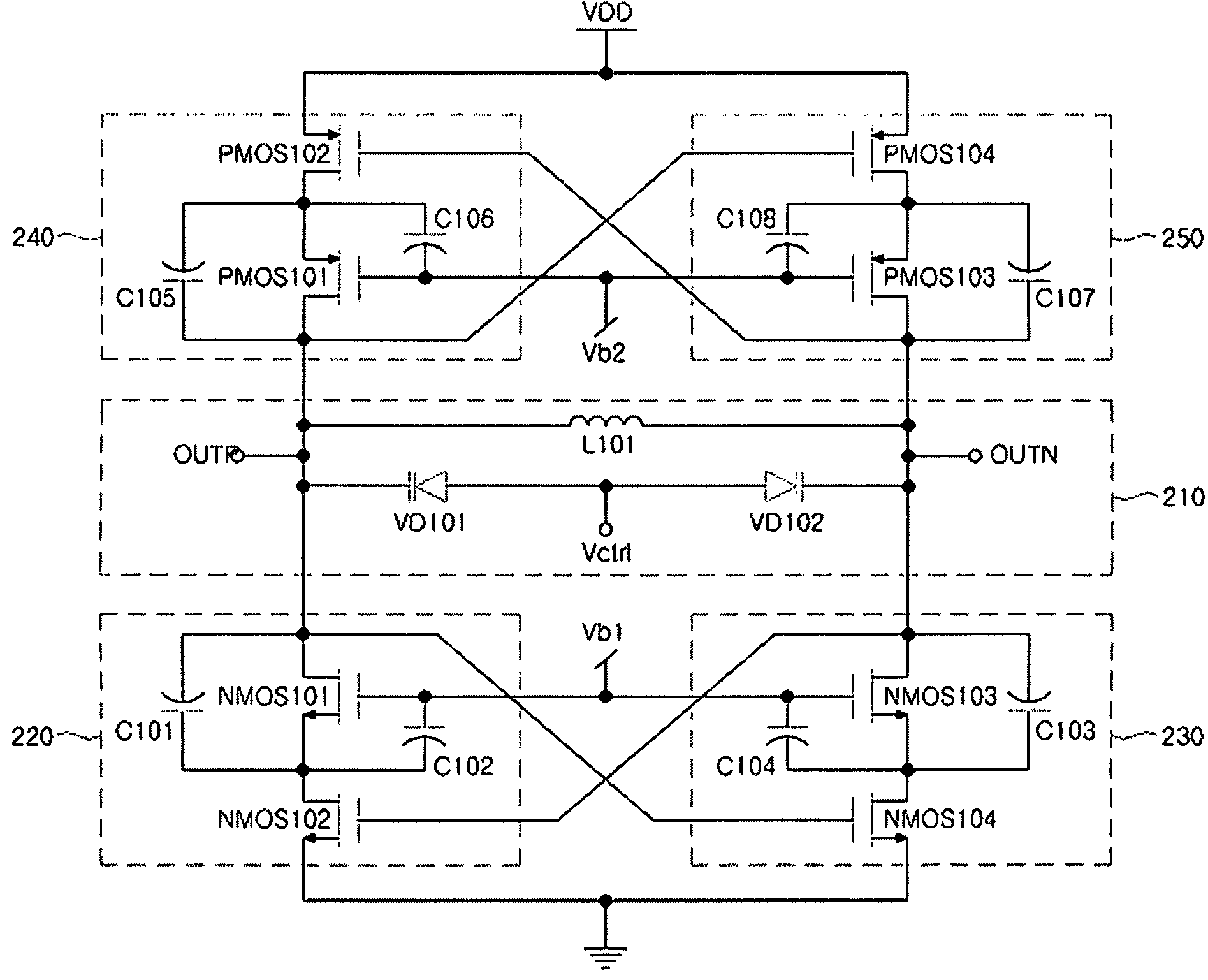
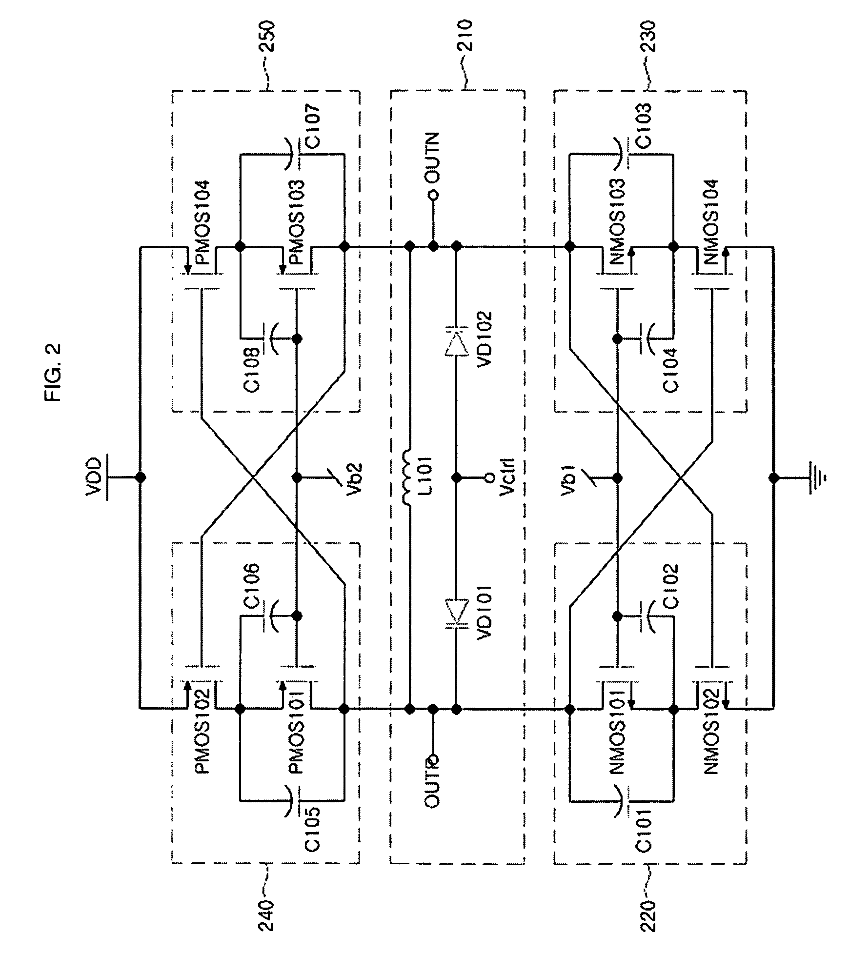
[0027]FIG. 2 is a circuit diagram of a differential cascode voltage-controlled oscillator using cascode amplifiers according to an embodiment of the present invention.

[0028]Referring to FIG. 2, a differential cascode voltage-controlled oscillator 200 includes an LC tank circuit 210, a first cascode amplifier 220, a second cascode amplifier 230, a third cascode amplifier 240, and a fourth cascode amplifier 250. The LC tank circuit 210 generates an AC signal with a certain frequency. The first cascode amplifier 220 amplifies an AC signal generated by the LC tank circuit 210 and outputs the resulting signal to an output terminal OUTP. The second cascode amplifier 230 amplifies an AC signal generated by the LC tank circuit 210 and outputs the resulting signal to an output terminal OUTN. The third cascode amplifier 240 amplifies an AC signal generated by the LC tank circuit 210...


PUM


Abstract

Provided is a differential cascode voltage-controlled oscillator that can reduce a phase noise by the use of a quality factor enhancement technique with negative conductance and can mitigate a ground-caused noise effect by the use of a cascode connection technique. The differential cascode voltage-controlled oscillator includes an AC signal generator, and first through fourth cascode amplifiers. The AC signal generator generates an AC signal with a certain frequency according to a control voltage. The first cascode amplifier is connected in a cascode configuration, and amplifies the AC signal to output the resulting signal to a first output terminal. The second cascode amplifier is connected in a cascode configuration and connected to the first cascode amplifier in a cross-coupled configuration, to amplify the AC signal to output the resulting signal to a second output terminal. The third cascode amplifier is connected in a cascode configuration to amplify the AC signal to output the resulting signal to the first output terminal. The fourth cascode amplifier is connected in a cascode configuration and connected to the third cascode amplifier in a cross-coupled configuration, to amplify the AC signal to output the resulting signal to the second output terminal. Herein, the first and second cascode amplifiers and the third and fourth cascode amplifiers are symmetrically connected to differentially amplify the AC signal.

Description

CROSS-REFERENCE TO RELATED APPLICATIONS[0001]This application claims priority under 35 U.S.C. §119 to Korean Patent Application No. P2007-96921, filed in Korea on Sep. 21, 2007, the disclosure of which is incorporated herein by reference in its entirety.BACKGROUND OF THE INVENTION[0002]1. Field of the Invention[0003]The present disclosure relates to a differential cascode voltage-controlled oscillator for generating a local signal at a transceiver in a wireless communication system, and more particularly, to a cascode amplifier with negative conductance and a differential cascode voltage-controlled oscillator using the cascode amplifier, which can reduce a phase noise by the use of a quality factor enhancement technique and can mitigate a ground-caused noise effect by the use of a cascode connection technique.[0004]This work was supported by the IT R&D program of MIC / IITA. [2006-S-071-02, Development of UWB Solution for High Speed Multimedia Transmission][0005]2. Description of the ...

Claims


Application Information

Patent Timeline
Patent Type & Authority Patents(United States)
IPC IPC(8): H03B5/12H03F3/191
CPCH03F1/223H03F1/26H03F3/19H03B5/1228H03B5/1212H03B5/1215H03B5/1243H03F2200/108H03F2200/372H03F2200/451H03F1/22
Inventor PARK, BONG-HYUKLEE, SEUNG-SIKJANG, SEUNG-HYUNCHOI, SANG-SUNG
Owner ELECTRONICS & TELECOMM RES INST
Why Eureka
Try Eureka