Tunable patch antenna of planar construction

Active Publication Date: 2010-10-26
KATHREIN AUTOMOTIVE GMBH
View PDF17 Cites 15 Cited by
  • Summary
  • Abstract
  • Description
  • Claims
  • Application Information

AI Technical Summary

Benefits of technology

[0015]An important advantage is produced in that influencing of the antenna pattern is possible with the antenna in a simple manner without a considerable outlay for additional components that are complicated to produce under certain circumstances, or even only a fine tuning, being necessary. Expensive special development or expensive production of additional parts is therefore avoided. However, the fact that in the scope of the invention, conventional c

Problems solved by technology

The disadvantage in all previously known antenna arrangements of this type is the comparatively complex construction.
This generally requires not only a more complex development, but frequently also leads to an increase in the production costs.
Moreover, the previously known measures for achieving a tunable patch antenna can frequently also not be applied or transferred to conventional commercial ceram

Method used


Image

  • Tunable patch antenna of planar construction
  • Tunable patch antenna of planar construction
  • Tunable patch antenna of planar construction

Examples


Embodiment Construction

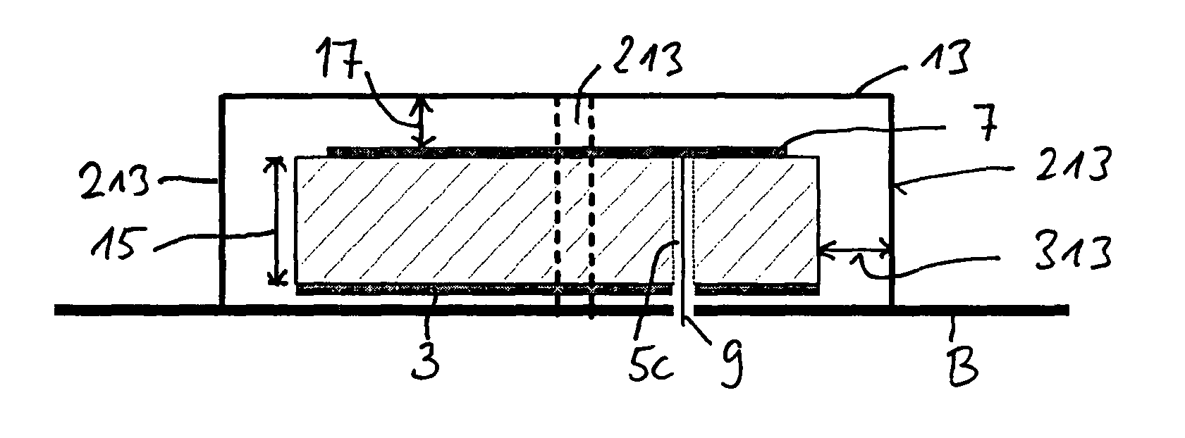
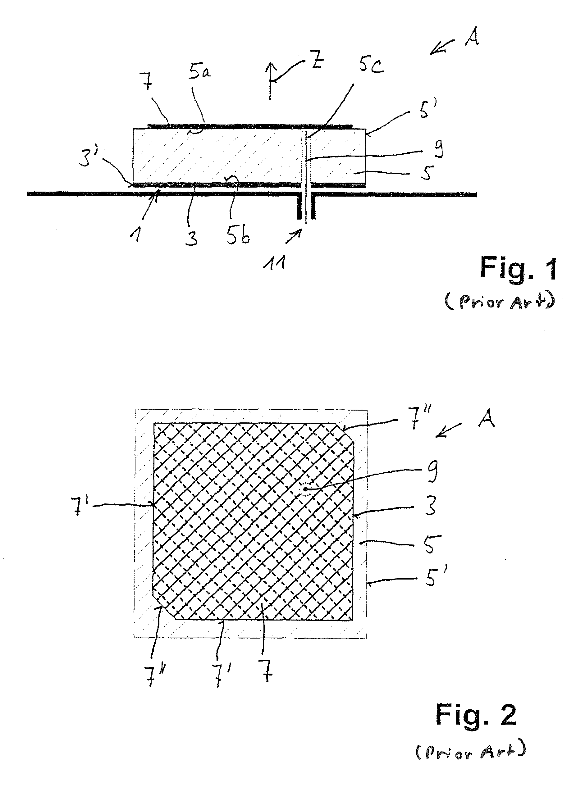
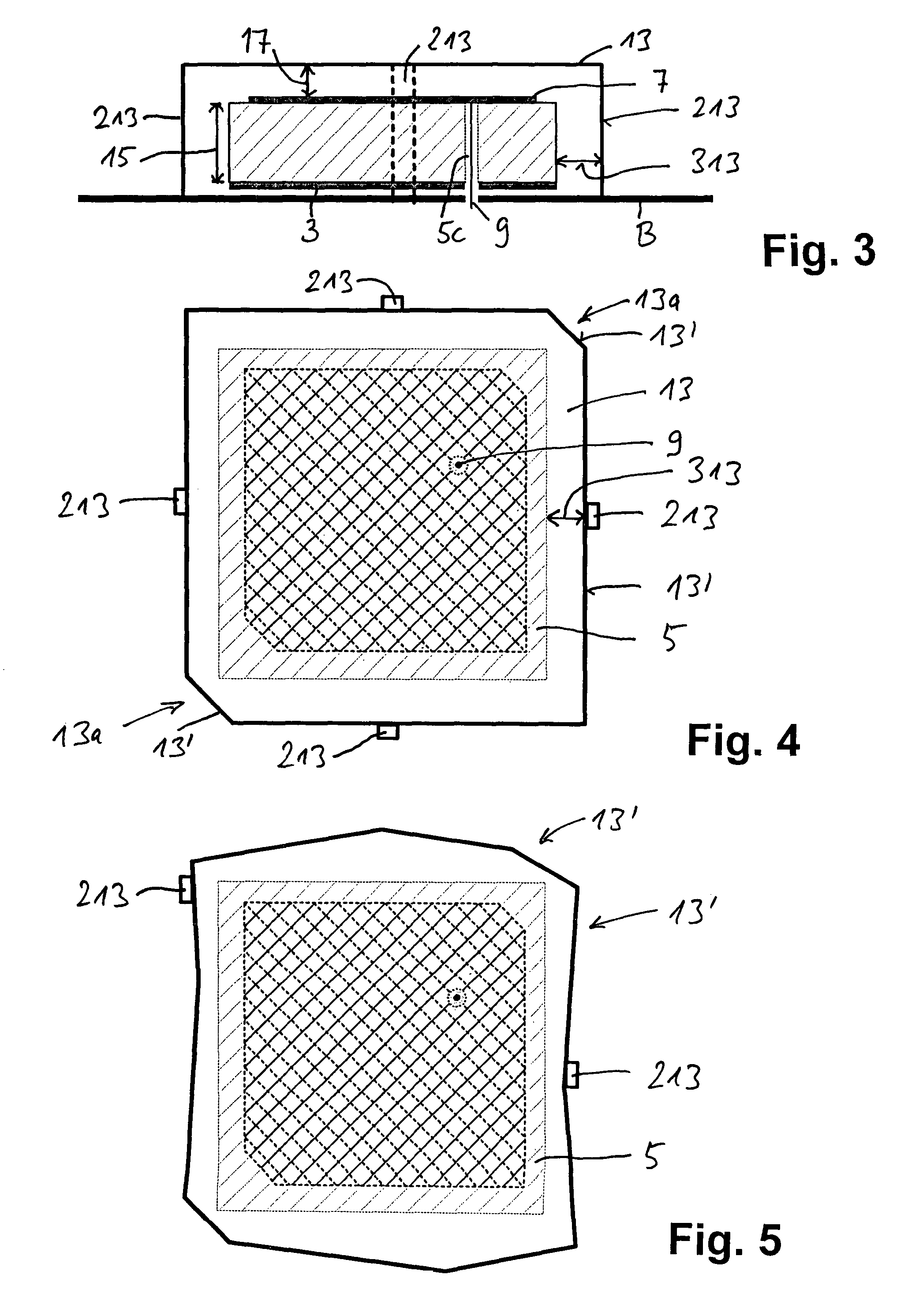
[0036]FIG. 1 shows a schematic lateral view and FIG. 2 a schematic plan view of the basic structure of a conventional commercial patch radiator A (patch antenna), which is extended with the aid of FIG. 3 et seq. into a tunable patch antenna.

[0037]The patch antenna shown in FIGS. 1 and 2 comprises a plurality of surfaces and layers arranged along an axis Z one above the other, which will be dealt with below.

[0038]It can be seen from the schematic cross-sectional view according to FIG. 1 that the patch antenna A has an electrically conductive ground surface 3 on its so-called lower or mounting side 1. Arranged on the ground surface 3 or with a lateral offset with respect thereto is a dielectric carrier 5, which generally has an outer contour 5′ in plan view, which corresponds to the outer contour 3′ of the ground surface 3. This dielectric carrier 5 may, however, also have larger or smaller dimensions and / or be provided with an outer contour 5′ differing from the outer contour 3′ of t...


PUM


Abstract

An improved tunable antenna of planar construction is distinguished by the following features:
    • in plan view perpendicular to the effective surface (7), the electrically conductive structure (13, 113) completely or partially covers the effective surface (7),
    • the electrically conductive structure (13, 113) is coupled and/or connected galvanically or capacitively or serially and/or with interposition with at least one electrical component (125) with the ground surface (3) and/or a chassis (B) located on a potential or ground.

Description

FIELD[0001]The invention relates to a tunable antenna of planar construction.BACKGROUND AND SUMMARY[0002]Patch antennas or so-called microstrip antennas have been known for a long time. They generally comprise an electrically conductive base surface, a dielectric carrier material arranged thereabove and an electrically conductive effective surface provided on the upper side of the dielectric carrier material. The upper effective surface is generally excited by a feed line extending transversely to the above-mentioned planes and layers. A coaxial cable is primarily used as the connection cable, the external conductor of which is electrically connected at a connection to the ground conductor, whereas the internal conductor of the coaxial cable is electrically connected to the effective surface located at the top.[0003]A tunable microstrip antenna is known, for example, from U.S. Pat. No. 4,475,108. Integrated varactor diodes are used for frequency tuning in this patch antenna.[0004]Th...

Claims


Application Information

Patent Timeline
IPC IPC(8): H01Q5/00
CPCH01Q9/0414H01Q9/0442H01Q9/0457H01Q19/005H01Q5/00H01Q9/04H01Q13/08H01Q19/00
Inventor SCHILLMEIER, GERALDMIERKE, FRANK
Owner KATHREIN AUTOMOTIVE GMBH
Why Eureka
Try Eureka