Refrigerant cycle device

a cycle device and refrigerant technology, applied in the direction of cooling fluid circulation, lighting and heating apparatus, domestic cooling apparatus, etc., can solve the problems of loss of kinetic energy of refrigerant, reduced expansion, and reduced dynamic pressure of refrigeran

Inactive Publication Date: 2010-11-02
DENSO CORP
View PDF25 Cites 55 Cited by
  • Summary
  • Abstract
  • Description
  • Claims
  • Application Information

AI Technical Summary

Benefits of technology

[0012]In the refrigerant cycle device, the branch portion can be located to maintain a dynamic pressure of the refrigerant flowing out of the ejector, and the second evaporator is connected to the branch portion in a range where the dynamic pressure of the refrigerant flowing out of the ejector is applied to an inside of the second evaporator. This surely allows the refrigerant to flow into the second evaporator, as compared to a case in which only the pressure difference between the static pressures causes the refrigerant to flow into the second evaporator. As a result, the second evaporator connected to the refrigerant suction port of the ejector can obtain an appropriate refrigeration capacity.
[0013]The suction side of the compressor is connected to the downstream side of the first evaporator, so that the operation of the compressor surely enables the refrigerant to flow into the first evaporator. Thus, the first evaporator can also obtain an appropriate refrigeration capacity. As a result, the refrigeration capacity of the entire cycle can be improved in the refrigerant cycle device.
[0015]According to another aspect of the present invention, the branch portion and the second evaporator are connected without a throttling therebetween such that the dynamic pressure of the refrigerant flowing out of the ejector is applied to the inside of the second evaporator Therefore, the dynamic pressure at the outlet of the ejector can be easily applied to the inside of the second evaporator.
[0018]As an example, a throttle device may be provided for decompressing and expanding the refrigerant in a refrigerant flow path from the branch portion to the inlet of the second evaporator. Accordingly, the above relationship can be easily set using the throttle device.
[0021]According to another aspect of the present invention, an operation method of a refrigerant cycle device includes a step of compressing and discharging refrigerant from a compressor; a step of cooling high-temperature and high-pressure refrigerant discharged from the compressor by using a radiator; a step of decompressing and expanding the refrigerant on a downstream side of the radiator in a nozzle portion of an ejector, while sucking refrigerant through a refrigerant suction port of the ejector by a refrigerant flow jetted from the nozzle portion at high velocity; a step of branching a flow of the refrigerant flowing out of the ejector into at least a first refrigerant stream and a second refrigerant stream; a step of evaporating the refrigerant of the first refrigerant stream branched by the branch portion in a first evaporator to allow the refrigerant to flow to a suction side of the compressor; and a step of evaporating the refrigerant of the second refrigerant stream branched by the branch portion in a second evaporator to allow the refrigerant to flow to an upstream side of the refrigerant suction port. Furthermore, the step of the branching is performed to maintain a dynamic pressure of the refrigerant flowing out of the ejector and to apply the dynamic pressure of the refrigerant flowing out of the ejector to an inside of the second evaporator. As a result, the second evaporator connected to the refrigerant suction port of the ejector can obtain an appropriate refrigeration capacity.

Problems solved by technology

The inventors have studied about the cause for this problem, and found that the problem is due to arranging a throttle device on the upstream side of the second evaporator.
The reason for this is that the decompression and expansion of the refrigerant by the throttle device results in a loss of kinetic energy of the refrigerant, so that a dynamic pressure of the refrigerant after the decompression and expansion is decreased as compared to that of the refrigerant before the decompression and expansion.
That is, when the dynamic pressure of the refrigerant after the decompression and expansion is decreased, the dynamic pressure at the outlet of the ejector cannot be applied to refrigerant on the downstream side of the throttle device.
When the vapor / liquid separator is disposed on the upstream side of the throttle device, like the cycle as disclosed in JP-A-3-291465, the separation of the refrigerant into the liquid and vapor phases at the vapor / liquid separator also results in the loss of the kinetic energy of the refrigerant with little dynamic pressure of the refrigerant after the decompression and expansion.
As a result, the second evaporator may not obtain the refrigeration capacity.

Method used


Image

  • Refrigerant cycle device
  • Refrigerant cycle device
  • Refrigerant cycle device

Examples


first embodiment

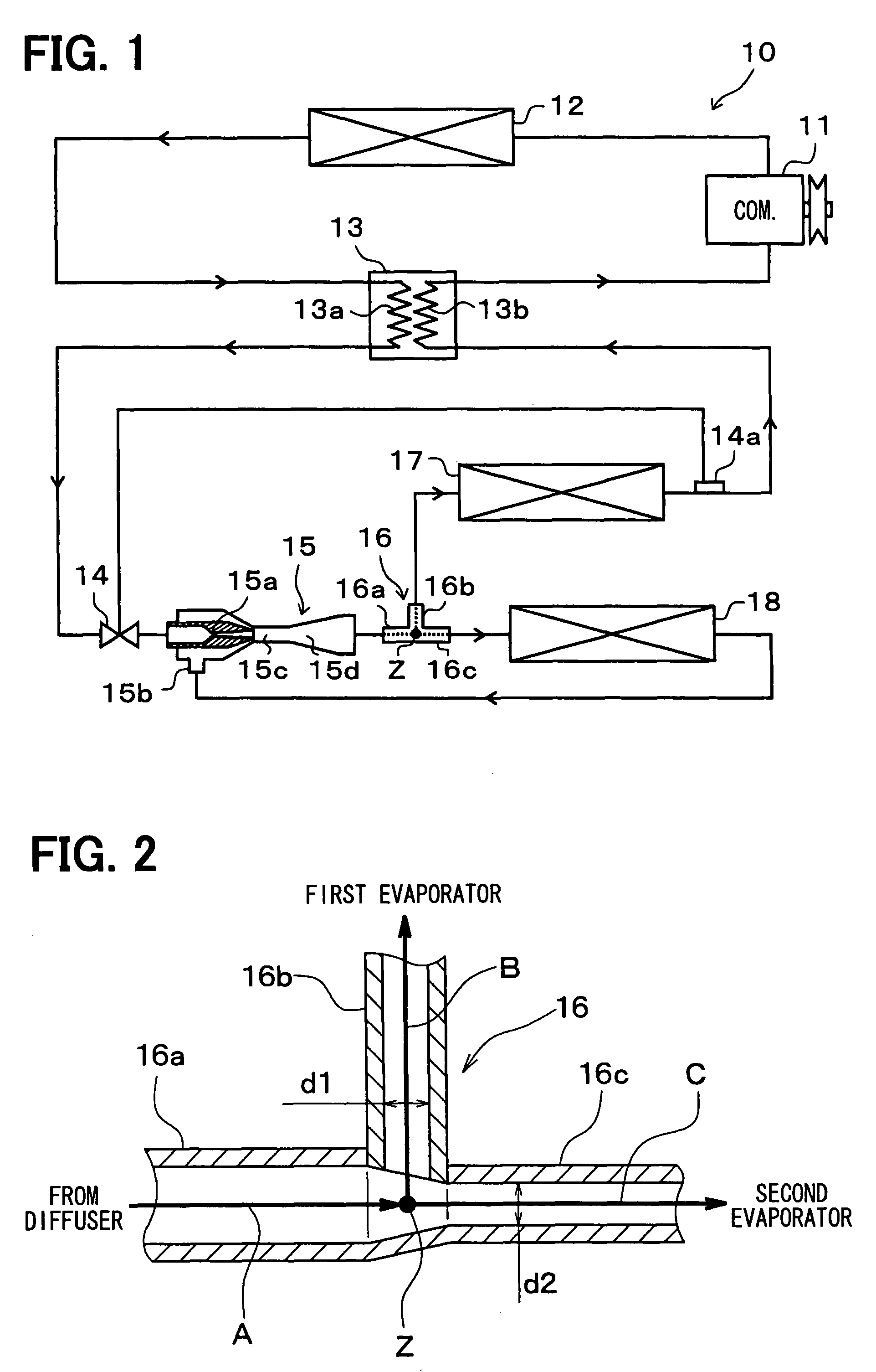
[0041]A first embodiment of the invention will be described below with reference to FIGS. 1 to 3. A refrigerant cycle device 10 includes a refrigerant cycle in which refrigerant is circulated. In the refrigerant cycle, a compressor 11 is located to suck, compress, and then discharge the refrigerant. The compressor 11 is rotatably driven by a driving force transmitted from an engine for vehicle running (not shown) via a pulley and a belt, for example.

[0042]As the compressor 11, may be used either of a variable displacement compressor for being capable of adjusting a refrigerant discharge capacity depending on a change in discharge capacity, or a fixed displacement compressor for adjusting a refrigerant discharge capacity by changing an operating efficiency of the compressor by intermittent connection of an electromagnetic clutch. The use of an electric compressor as the compressor 11 can adjust the refrigerant discharge capacity by adjustment of the number of revolutions of an electr...

second embodiment

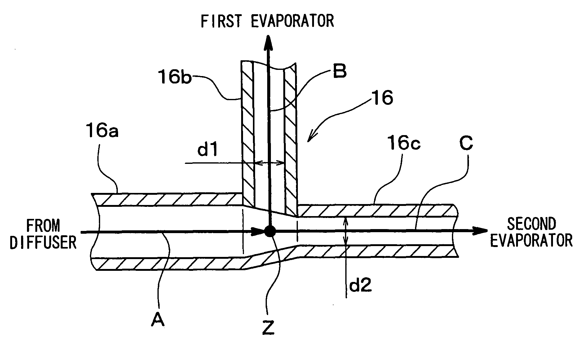
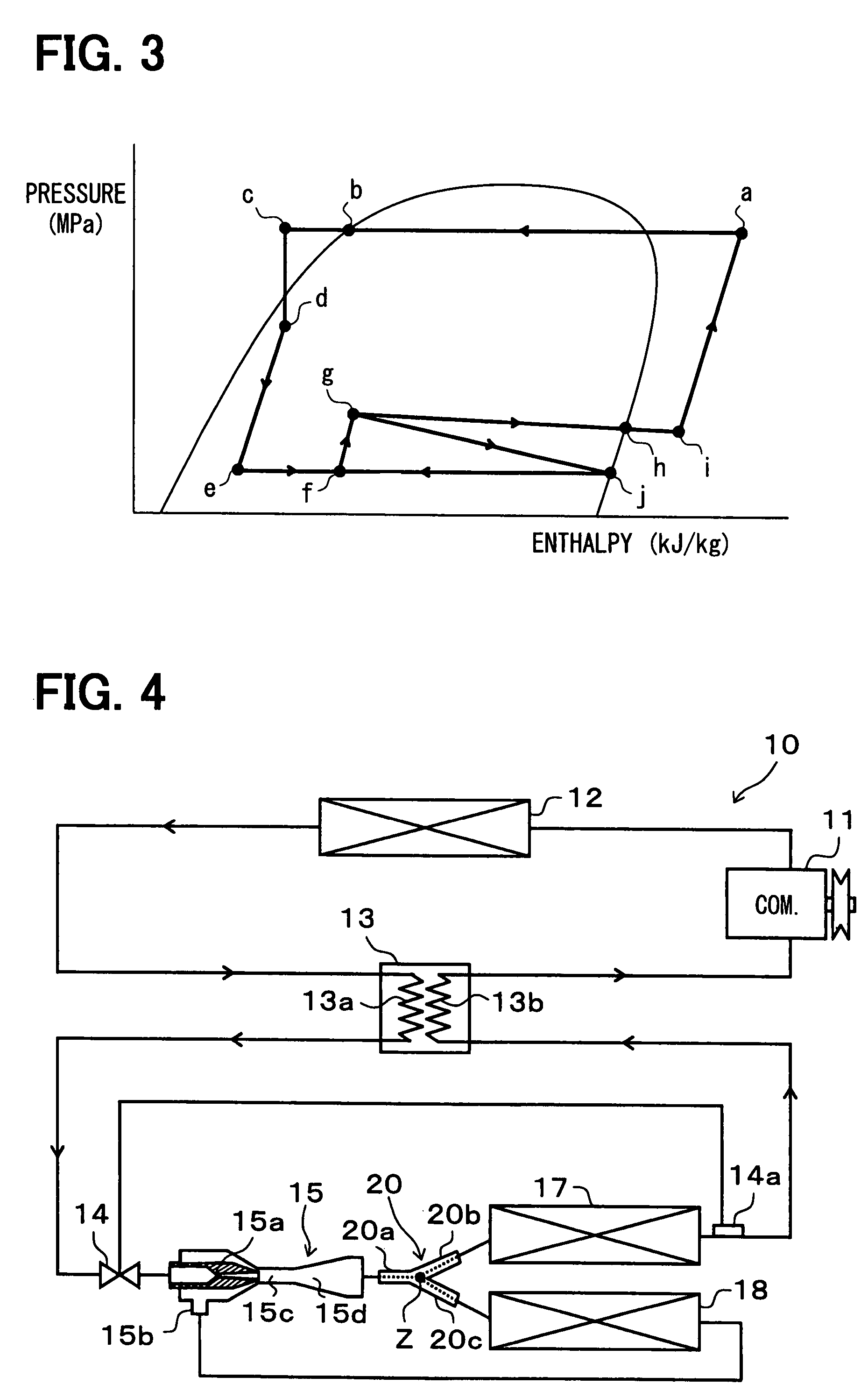
[0088]In the above-described first embodiment, the refrigerant distribution unit 16 having a T-shaped joint structure is employed. A refrigerant cycle device 10 of the second embodiment employs a refrigerant distribution unit 20 having a Y-shaped three-way joint structure as shown in FIGS. 4 and 5. The structures of other components in the refrigerant cycle device 10 may be the same as those in the first embodiment. FIG. 4 is a schematic diagram showing the refrigerant cycle device 10 of the second embodiment. FIG. 5 is a sectional view in the axial direction of an introduction pipe 20a of the refrigerant distribution unit 20.

[0089]The refrigerant distribution unit 20 includes, as shown in FIG. 5, the introduction pipe 20a for allowing the refrigerant to flow thereinto, a first leading pipe 20b for allowing the refrigerant to flow to the first evaporator 17, and a second leading pipe 20c for allowing the refrigerant to flow to the second evaporator 18.

[0090]Specifically, the introdu...

third embodiment

[0096]In the third embodiment, the structure of the refrigerant distribution unit 16 described in the first embodiment is used. As shown in the entire construction diagram of FIG. 6, a convergent nozzle 21 (taper nozzle) serving as a throttle device for decompressing the refrigerant is provided between the refrigerant distribution unit 16 (specifically, the second leading pipe 16c) and the second evaporator 18, in addition to the refrigerant cycle structure of the first embodiment. The static and dynamic pressures of the refrigerant at points D, E, F and G in FIG. 6 are adjusted to have the following formula F1.

[0097]Specifically, the point D is an outlet of the diffuser portion 15d of the ejector 15, the static pressure of the refrigerant at the point D (i.e., the refrigerant at the outlet of the diffuser portion 15d) is Ps1, and the dynamic pressure thereof is Pv1. The point E is an inlet of the second evaporator 18, the static pressure of the refrigerant at the point E (i.e., ref...


PUM


Abstract

In a refrigerant cycle device having an ejector, a branch portion for branching a flow of refrigerant flowing out of the ejector into at least a first refrigerant stream and a second refrigerant stream is located. A first evaporator for evaporating the refrigerant of the first refrigerant stream is located to allow the refrigerant to flow to a suction side of the compressor, and a second evaporator for evaporating the refrigerant of the second refrigerant stream is located to allow the refrigerant to flow to an upstream side of a refrigerant suction port of the ejector. In addition, the branch portion is located to maintain a dynamic pressure of the refrigerant flowing out of the ejector, and the second evaporator is connected to the branch portion in a range where the dynamic pressure can be applied to an inside of the second evaporator.

Description

CROSS REFERENCE TO RELATED APPLICATION[0001]This application is based on Japanese Patent Application No. 2006-292347 filed on Oct. 27, 2006, the contents of which are incorporated herein by reference in its entirety.FIELD OF THE INVENTION[0002]The present invention relates to a refrigerant cycle device including an ejector, and an operating method of the refrigerant cycle device.BACKGROUND OF THE INVENTION[0003]Conventionally, JP-A-3-291465 discloses a refrigerant cycle device including an ejector. In the refrigerant cycle device as disclosed in JP-A-3-291465, a vapor / liquid separator for separating refrigerant into liquid and vapor phases is disposed on the downstream side of the ejector. The vapor / liquid separator separates the flow of refrigerant into one flow which is to be sucked into a compressor, and the other flow which is to be sucked into a refrigerant suction port of the ejector.[0004]A first evaporator is disposed between the vapor / liquid separator and the compressor, an...

Claims


Application Information

Patent Timeline
Patent Type & Authority Patents(United States)
IPC IPC(8): F25B49/00
CPCF25B41/00B60H2001/3298F25B5/02F25B40/00F25B2341/0011F25B2700/21175F25B1/00F25B43/00
Inventor TAKEUCHI, HIROTSUGUIKEGAMI, MAKOTONISHIJIMA, HARUYUKI
Owner DENSO CORP
Why Eureka
Try Eureka