Method for forming masonry unit

a technology of masonry unit and masonry, which is applied in the direction of foundry moulding apparatus, building repairs, foundry patterns, etc., can solve the problems of reducing the productivity and inexpensiveness of bricks, affecting and unable to adjust the accuracy of masonry by fresh mortar, so as to improve the productivity of bricks and promote the efficiency of brick production process.

Inactive Publication Date: 2010-11-02
JAPAN SCI & TECH CORP
View PDF29 Cites 15 Cited by
  • Summary
  • Abstract
  • Description
  • Claims
  • Application Information

AI Technical Summary

Benefits of technology

[0017]According to this arrangement of the present invention, the upper and lower faces of the masonry unit are covered with the solidified covering material. The accuracy of surface of the solidified material depends on the accuracy of the surface of the mold. Therefore, a number of masonry units with the upper and lower faces improved in their dimensional accuracy can be produced with use of the prefabricated mold with high dimensional accuracy. Thus, high dimensional accuracy (the standard deviation=approx. 0.1 mm), flatness and horizontality of the lying faces are ensured without grinding of the lying faces (the upper and lower faces), whereby the productivity and inexpensiveness can be improved.
[0019]According to such an arrangement of this invention, the masonry unit is formed with the through-hole which is covered with the solidified covering material on its inner circumferential surface. The position and inner diameter of the hole depends on the position and outer diameter of the core, and the accuracy of the inner surface of the hole relies on the accuracy of an outer circumferential surface of the core. Therefore, it is not necessary to precisely make a through-hole in its final position and dimensions on the masonry unit (the blank or basic form of the masonry unit) to be inserted into the mold, but the unfinished through-hole (the basic through-hole) with an approximate dimension may be formed at an approximate position enclosing the final position of the hole. As the final dimension, position and accuracy of the hole depend on those of the core, the basic through-holes may have an equal or equivalent dimension and configuration, regardless of their final dimension, position and accuracy. Therefore, it is possible to omit a boring step for precisely or strictly boring the masonry unit with high accuracy, thereby further improving the productivity and inexpensiveness of the masonry units.
[0020]Further, the present invention provides a method with the aforementioned arrangement, wherein a brick having a generally rectangular profile is used as the masonry unit to be contained in the mold. The masonry unit, which has the lying face finished to be flat, smooth and horizontal by the solidified covering material, can be precisely laid by means of the interlayer metal plates, even though the grinding step is omitted. In addition, such masonry units are integrally assembled to be a dry type of masonry structure with high accuracy, by means of mechanical tightening forces of the nuts and bolts. Therefore, the masonry units formed in accordance with this forming method can be preferably used as the bricks for the DUP Construction Method.
[0022]In general, the hole formed in the brick baking process is decreased in positional and dimensional accuracy. It is difficult to use the hole of the brick formed in the brick baking process, as a hole of the brick for the DUP Construction Method. However, in a case where the inner surface of the hole can be covered with the covering material simultaneously with covering of the upper and lower surfaces, the through-hole and the bolt hole applicable to the DUP Construction Method can be formed in a conventional brick with high accuracy.
[0024]In a preferred embodiment of the present invention, when the masonry unit is contained in the mold, a space chargeable with the fluidic covering material is further defined between each of the end faces and the surface of the mold. Preferably, the space is in communication with the aforementioned space between the upper and lower surfaces and the surfaces of the mold. According to such an arrangement, the end face of the brick is also covered with the solidified covering material. The accuracy of the relative position of adjacent masonry units can be improved and the vertical joints can be precisely and relatively easily formed between the units.
[0030]The cement paste including a relatively large amount of fly ash can be preferably used as the covering material (for example, cement paste mixture containing 185 kg of water, 285 kg of portland cement and 455 kg of fly ash). Use of fly ash is favorable from an aspect of recycling of waste, since a by-product of a coal-fueled power plant can be effectively used. Further, fluidity of the covering material is obtained by action of fly ash promoting fluidity, and therefore, use of fly ash is advantageous for densely charging the material within the space in the mold.

Problems solved by technology

However, according to this method, the walls, columns and so forth are built by fastening the bricks with the nuts and bolts, and therefore, adjustment of accuracy of masonry by fresh mortar can not be carried out.
However, the steps for grinding the bricks after baking cause losses of water and energy for grinding, and the steps for grinding the bricks also result in losses of productivity and inexpensiveness of the bricks since the steps complicate the production process, waste time, cause addition of work or steps, increase production costs including labor costs, and create a shavings disposal problem and so forth.
However, such boring steps for making these holes also cause losses of productivity and inexpensiveness of the bricks.

Method used


Image

  • Method for forming masonry unit
  • Method for forming masonry unit
  • Method for forming masonry unit

Examples


Embodiment Construction

[0049]With reference to the attached drawings, a preferred embodiment of the present invention is described hereinafter.

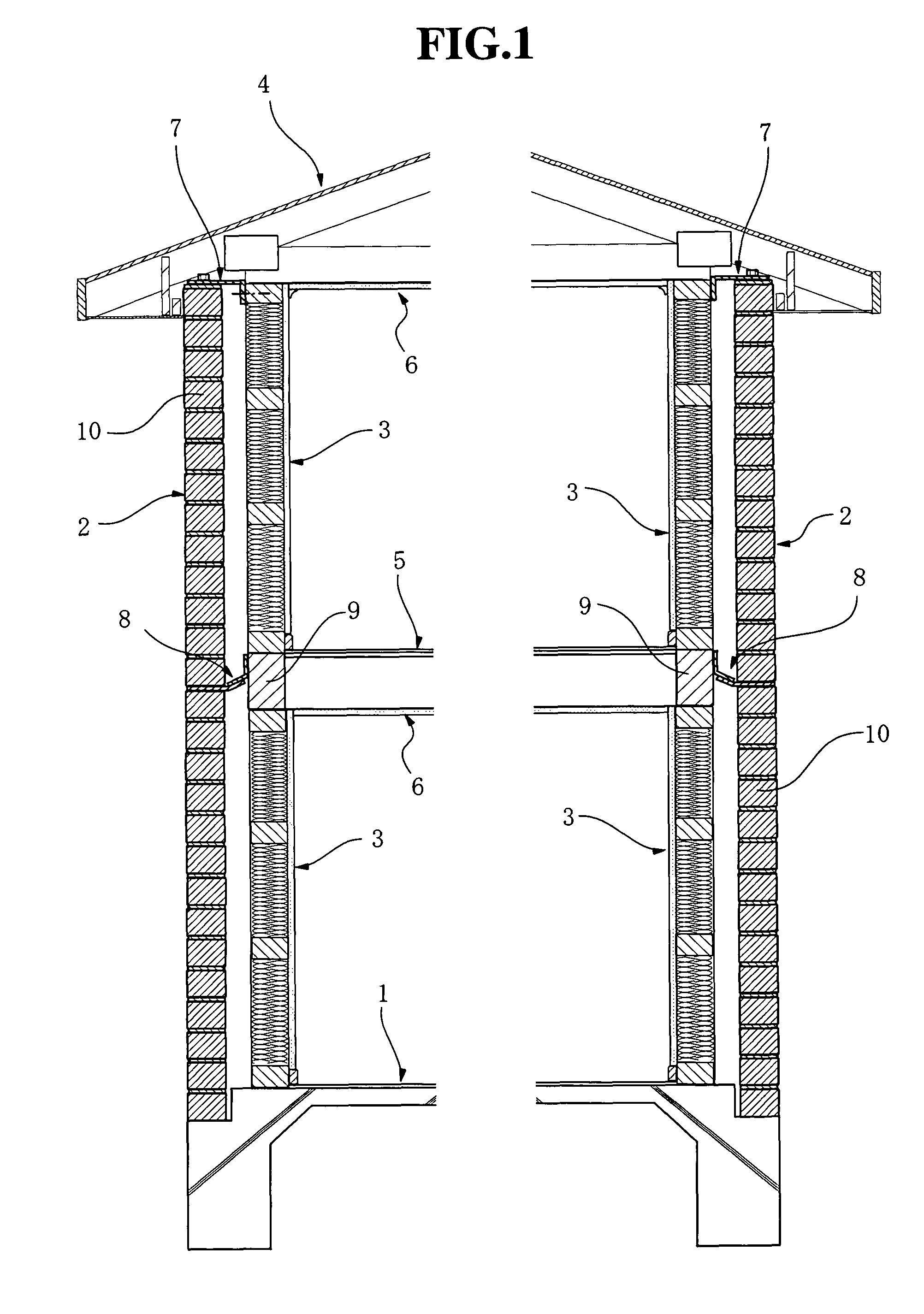
[0050]FIG. 1 is a cross-sectional view illustrating an architecture with brick walls constructed in accordance with DUP Construction Method.

[0051]The architecture is provided with a foundation and floor slab 1, outer walls 2, inner walls 3, a second floor framing 5, ceilings 6, a roof truss 4, and roofing materials (not shown). The outer walls 2 are brick walls laid on the foundation and floor slab 1 in accordance with the DUP Construction Method. The inner walls 3 are constructed by wooden panels which are conventionally used in a two-by-four wooden construction. The walls 3 are built up on the foundation and floor slab 1. The roof truss 4 is supported by upper ends of the inner walls 3. The roofing materials are provided on an upper surface of the roof truss 4. The load of the roof truss 4 acts on the inner walls 3 as a vertical load, which are supported by the l...


PUM

PropertyMeasurementUnit
thicknessaaaaaaaaaa
lengthaaaaaaaaaa
heightaaaaaaaaaa

Abstract

Masonry units (10) are integrally assembled by tightening forces of bolts (60) and nuts (70), in a condition that interlayer metal plates (50) are interposed between the masonry units. A basic form (11) of the masonry unit is contained in a mold for forming the masonry unit. A space (98) for fluidic covering material, which is chargeable with the covering material, is defined between upper and lower faces of the form (11), and the fluidic covering material is charged in the space. The upper and lower faces of the masonry unit are covered with the solidified covering material (12). According to the present invention, high dimensional accuracy of the masonry unit can be ensured, and efficiency of the production process of the masonry units is promoted to improve productivity of the masonry units.

Description

[0001]This is a national stage of International application no. PCT / JP2005 / 012283 filed on Jun. 28, 2005 and published in Japanese.TECHNICAL FIELD[0002]The present invention relates to a method of forming a masonry unit, and more specifically, to such a method for producing the masonry unit which is used in a dry type of masonry construction method utilizing mechanical tightening force.TECHNICAL BACKGROUND[0003]A variety of architectural structures are known in the art, such as wooden structure, reinforced concrete structure, steel structure and so forth. As a kind of such an architectural structure, a masonry structure is known, in which walls and so forth are constructed by laying or stacking masonry units such as bricks or concrete blocks.[0004]Bricks produced by baking a quantity of brick clay at a high temperature are highly evaluated by their architectural design effects or aesthetic effects resulting from their textures, stately appearances, feelings, colors and so forth. The...

Claims


Application Information

Patent Timeline
Patent Type & Authority Patents(United States)
IPC IPC(8): B22C9/24
CPCB28B7/183B28B13/0275B28B19/0053E04B2/16E04B2002/0254C04B41/85E04B2/02
Inventor MATSUFUJI, YASUNORIKOYAMA, TOMOYUKI
Owner JAPAN SCI & TECH CORP
Why Eureka
Try Eureka