Crawler without steel cores

a technology of steel cores and crawlers, applied in endless track vehicles, mechanical equipment, transportation and packaging, etc., can solve the problems of increased rework for disposal, reduced fuel efficiency, and inability to smoothly transfer driving power of crawlers, etc., to suppress the generation of deflection forces, suppress the deflection forces, and eliminate the separation of crawlers

Active Publication Date: 2010-11-02
TAERYUK RUBBER BELT
View PDF13 Cites 7 Cited by
  • Summary
  • Abstract
  • Description
  • Claims
  • Application Information

AI Technical Summary

Benefits of technology

[0014]According to the present invention, the symmetrically disposed separation preventing steel cords, having the same oblique angle with respect to the center portion in the driving direction of the crawler, suppress the generation of the deflection force and balance the deflection forces unbalancedly functioning laterally, thereby eradicating separation of the crawler.
[0015]In addition, by suppressing the deflection forces, the guide roller is prevented from riding the guide projection formed on the inward surface of the crawler, the lifetime of the crawler is remarkably extended, the oscillation is reduced, and the driving condition is improved, thereby the driver's fatigue being greatly lessened.

Problems solved by technology

Conventionally, since the crawler is made from rubber material so that the spaces between the sprocket pits are easily broken, the crawler cannot fulfill the duty of smoothly transferring the driving power.
However, when the conventional crawler, in which steel cores are included, is destroyed by fire for disposal, the cores do not burn up, and this causes additional rework for disposal.
Further, the increased weight of the crawler due to the cores reduces the fuel efficiency, and the separation occurs more frequently than a general sprocket-driving type.
In addition, since the friction between the metallic sprocket and the steel cores accelerates the abrasion, the lifetime of the product becomes short.
However, even though the prior art patent has the above advantages, it cannot avoid separation of the crawler because the deflection force, which is a common phenomenon for every crawler, is still generated.

Method used


Image

  • Crawler without steel cores
  • Crawler without steel cores
  • Crawler without steel cores

Examples


Embodiment Construction

[0026]Hereinafter, preferred embodiments of the present invention will be described in detail with reference to the attached drawings.

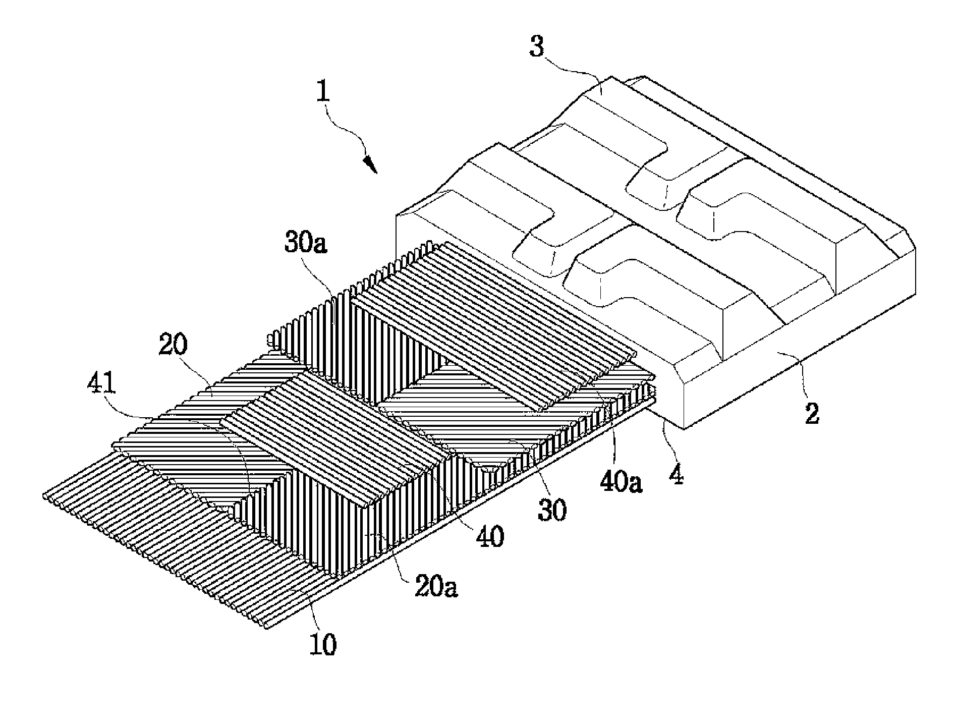
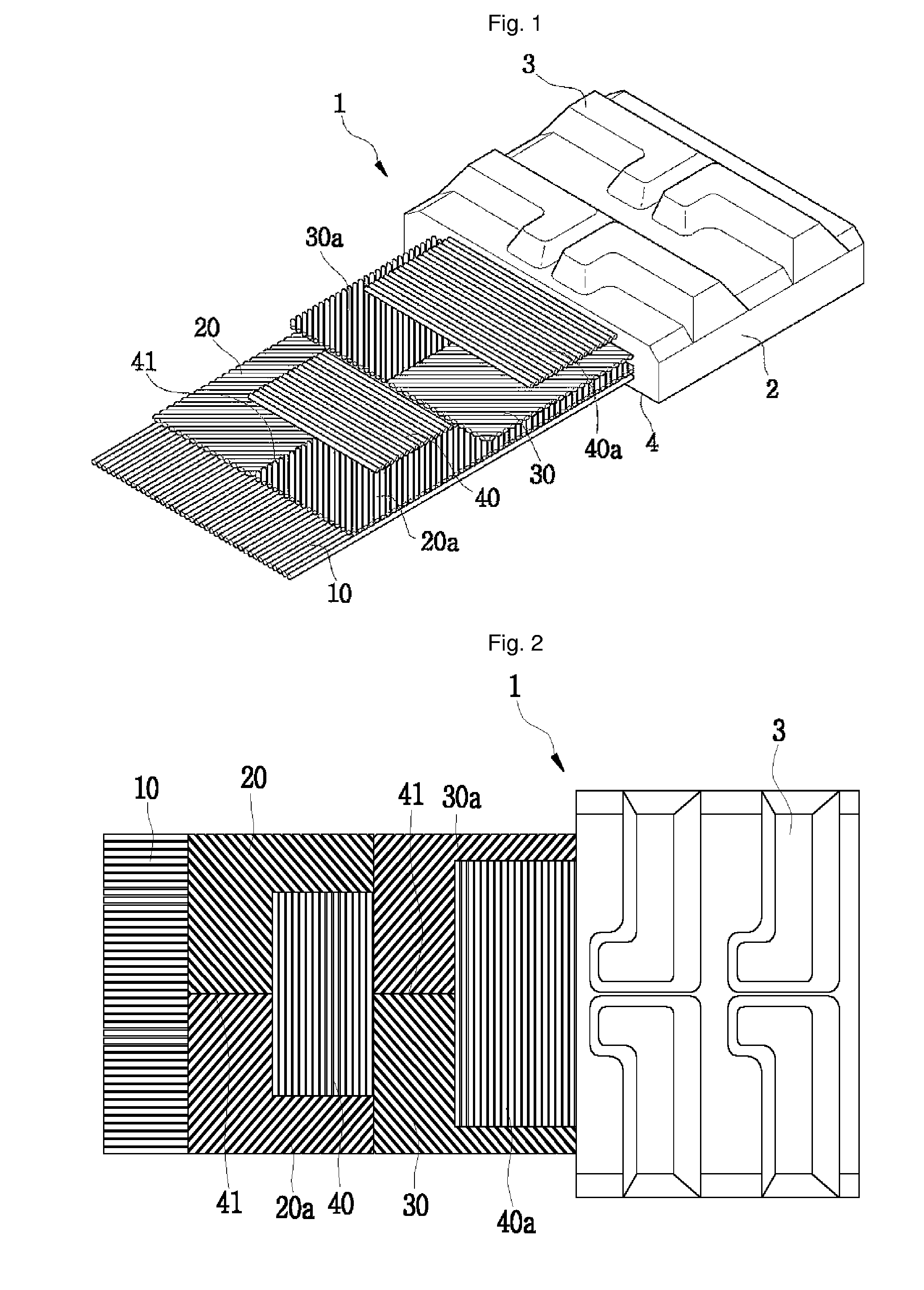
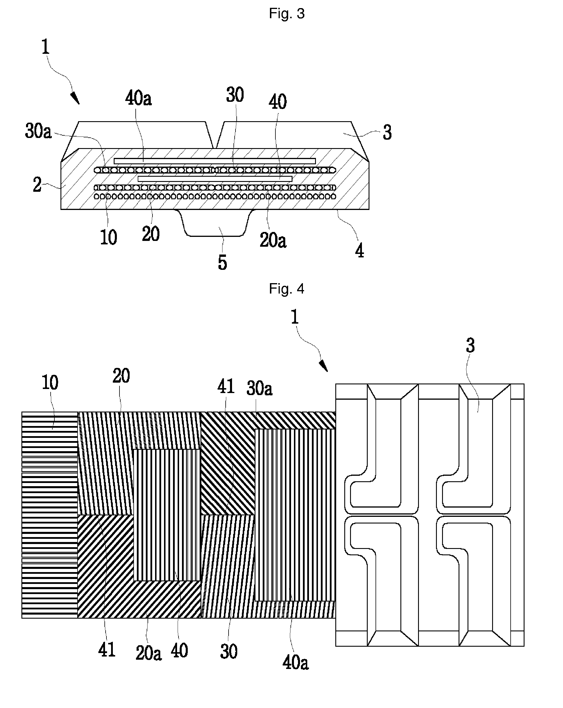
[0027]Basically, a crawler according to the present invention does not include steel cores, and therefore, the problems that the conventional crawler with steel cores has had can be eradicated. In addition, since the present invention employs various forms of steel cords inserted in the crawler body, the steel cords effectively suppress the deflection force generation that every crawler 1 have commonly had, and balance minute part of the deflection force functioning laterally, so that separation of the crawler can be essentially prevented.

[0028]With reference to FIG. 1, the basic construction of a coreless crawler 1 according to the present invention includes a plurality of lugs 3 formed on an outward surface of a crawler body 2 so that they come into contact with the ground; a plurality of guide projections 5 arrayed on an inward surface of the body ...


PUM


Abstract

The present invention relates to a crawler without steel cores (hereinafter referred to as “coreless crawler”), which is used for transporting the caterpillar vehicles for construction, civil engineering, agricultural use or the like. More particularly this invention relates to a coreless crawler for preventing the crawler body from being separated from a wheel or sprocket and the guide roller from riding the guide projection formed on the inward surface of the crawler, by disposing a pair of separation preventing steel cords having an oblique angle, symmetrically with respect to the center portion in the direction of driving so as to balance the deflection forces, thereby extending the lifetime of the crawler product.

Description

TECHNICAL FIELD[0001]The present invention relates to a crawler without steel cores (hereinafter referred to as “coreless crawler”), which is used for transporting the caterpillar vehicles for construction, civil engineering, agricultural use or the like. More particularly this invention relates to a coreless crawler for preventing the crawler body from being separated from a wheel or sprocket and the guide roller from riding the guide projection formed on the inward surface of the crawler, by disposing a pair of separation preventing steel cords having an oblique angle, symmetrically with respect to the center portion in the direction of driving so as to balance the deflection forces, thereby extending the lifetime of the crawler product.BACKGROUND ART[0002]A conventional crawler is suspended between a driving sprocket and an idler, and is given the forwarding force by the driving sprocket's rotation.[0003]The respective teeth of the driving sprocket are inserted in sprocket pits f...

Claims


Application Information

Patent Timeline
Patent Type & Authority Patents(United States)
IPC IPC(8): B62D55/253
CPCB62D55/244B62D55/253
Inventor SONG, IN-HYUK
Owner TAERYUK RUBBER BELT
Why Eureka
Try Eureka