
Live fluoroscopic roadmapping including targeted automatic pixel shift for misregistration correction

a fluoroscopic roadmap and automatic pixel shift technology, applied in the field of subtraction angiography, can solve the problems of inconvenient real-time correction, high cost, and high cost, and achieve the effect of reducing the cost of generating and applying accurate shift vectors

Active Publication Date: 2010-11-02
SIEMENS HEALTHCARE GMBH
View PDF11 Cites 29 Cited by
  • Summary
  • Abstract
  • Description
  • Claims
  • Application Information

AI Technical Summary

Benefits of technology

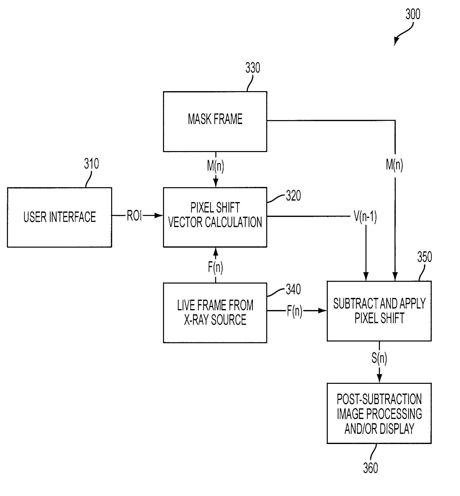
The present invention provides a system and method for correcting misregistration between frames in live fluoro roadmapping. The method uses a small region of interest (ROI) in an image to dynamically calculate a pixel shift vector, which is then used to shift the mask image frame before subtraction from the live image frame. This results in a live roadmapping frame with reduced motion between frames. The system allows users to control the focus of the dynamic correction and can seamlessly implement the function in the background process. The technical effects of the invention include improved accuracy and efficiency in live fluoro roadmapping.

Problems solved by technology

Like DSA, however, misregistration due to global and periodic motion, etc., can result in image artifacts in the subtracted live fluoro roadmapping, which degrade image quality.
The sampling and searching, however, is very operation intensive and not conducive to accurate real-time correction.
Accordingly, there is an inherent latency in updating or generating and applying an accurate shift vector to correct for, and minimize artifacts in the live roadmapping images.
While the conventional method may correct for gradual accumulated movement, such as the table being moved, or drifting of the source and / or detection device, it may be ineffective for periodic motion artifacts.
Nor will such a conventional shift vector-based method correct for motion in a targeted area that has a different motion artifact than another area that has not been searched and compared, for example, generated by motion that is coplanar with the X-ray detector.

Method used


Image

  • Live fluoroscopic roadmapping including targeted automatic pixel shift for misregistration correction
  • Live fluoroscopic roadmapping including targeted automatic pixel shift for misregistration correction
  • Live fluoroscopic roadmapping including targeted automatic pixel shift for misregistration correction

Examples


Embodiment Construction

[0017]The inventive methods, software and apparatus set forth herein are disclosed and described in order to convey the broad inventive concepts. The drawings and descriptions are not meant to in any way limit the scope and spirit of the inventions, as claimed.

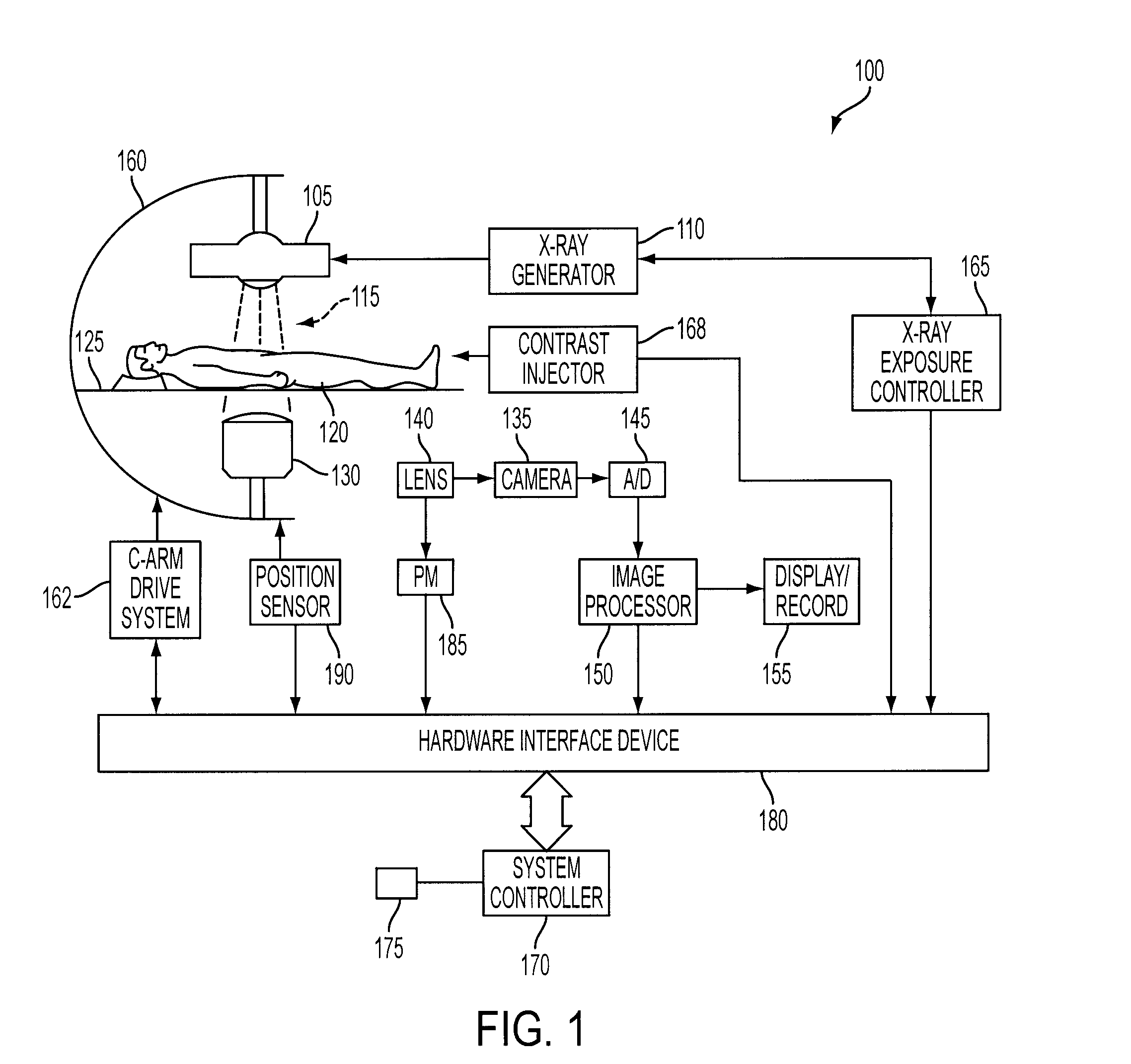
[0018]Reference will now be made in detail to exemplary embodiments of the present invention, examples of which are illustrated in the accompanying drawings, wherein like reference numerals refer to like elements throughout. The terms “process” and “method” are generally used to refer to a series of operations performed by a processor, be it a central processing unit of an x-ray system for live fluoro roadmapping, or a secondary processing unit of such a system. Useful machines for performing exemplary operations of the present invention include the AXIOM family of X-ray diagnostic imaging systems and products, by Siemens Medical Systems. The inventive method or process, however, is not limited to implementation on Siemens' X-...


PUM

PropertyMeasurementUnit
sizeaaaaaaaaaa
imagingaaaaaaaaaa
areaaaaaaaaaaa

Abstract

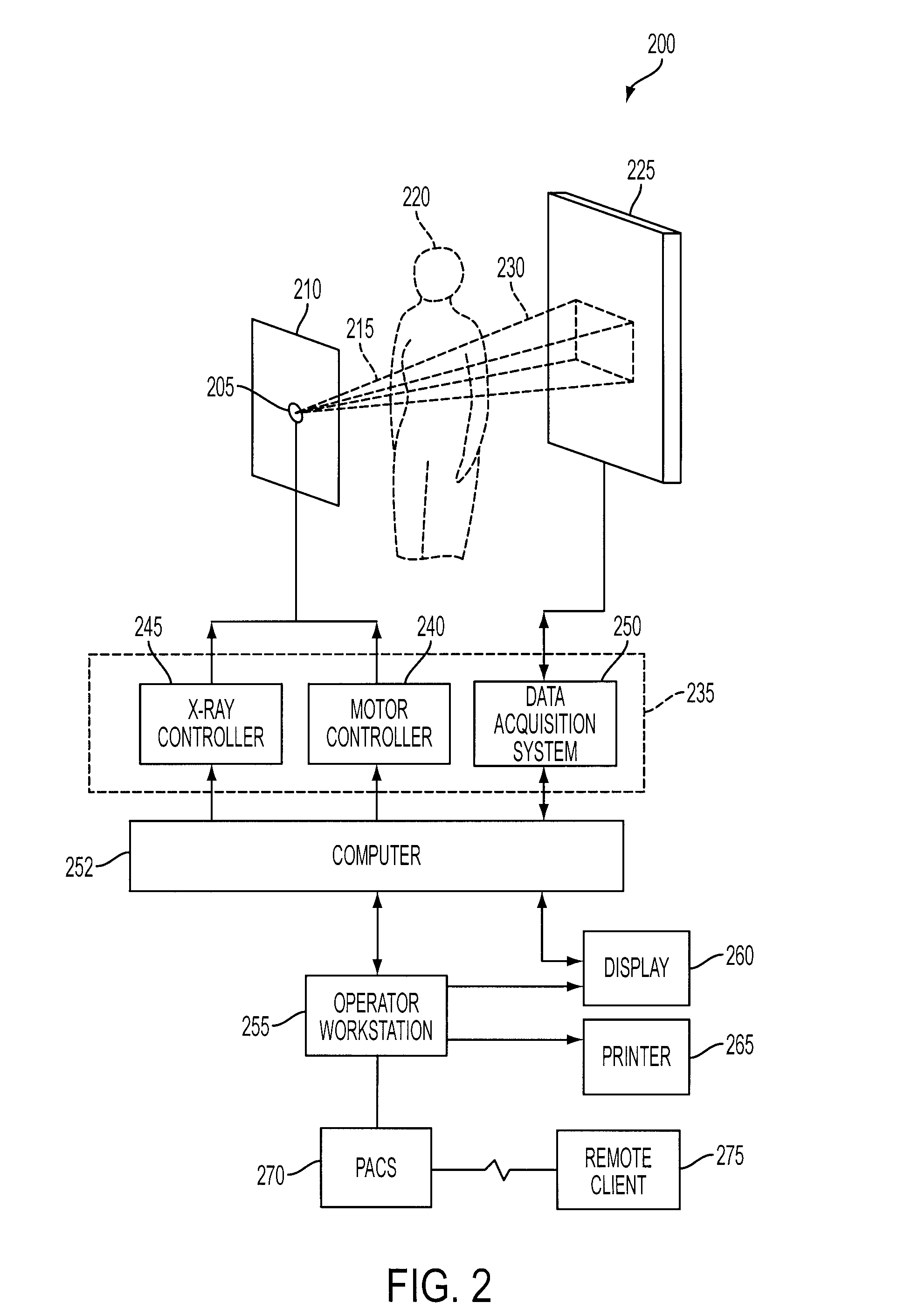
An X-ray diagnostic imaging system for conducting live fluoroscopic subtraction imaging is described as including an X-ray source for directing X-ray radiation to a patient being examined, an x-ray imaging device positioned for receiving the X-ray radiation and acquiring images in response thereto and a processor arranged in communication with the x-ray source and x-ray imaging device to control acquisition of a contrast-enhanced mask image frame and a live image frame without contrast enhancement, to conduct a pixel shift calculation operation based on a small, user-defined region of interest (ROI), for example, 1 / 16 of a full frame, to realize a pixel shift vector to correct for motion between live image frames, to shift pixels comprising the mask image frame by pixel shift directions defined by the pixel shift vector, and to subtract the shifted mask image frame from the live image frame to realize a live roadmapping image frame. The system includes a display for displaying the live roadmapping image frame, and a user interface that allows a user to define and capture the small ROI in the displayed image frame for use by the processor conducting the pixel shift calculation.

Description

PRIORITY CLAIM TO RELATED APPLICATION[0001]This application claims priority from U.S. Provisional Patent Application Ser. No. 60 / 834,446, filed Jul. 31, 2006, the disclosure of which is incorporated by reference in its entirety herein.BACKGROUND OF THE INVENTION[0002]The present invention relates to subtraction angiography, and more particularly relates to an X-ray diagnostic imaging system and method for dynamically targeting and instantaneously correcting for motion between acquired frames in angiographic roadmapping procedures.[0003]Angiography refers generally to the capture and representation of blood vessels or vasculature of the human body by means of X-ray imaging, i.e., X-ray vascular imaging. X-ray diagnostic imaging systems may be used for angiographic imaging procedures such as digital subtraction angiography (DSA), and live fluoroscopic roadmapping. Digital subtraction angiography or DSA is an imaging method used for visualizing blood vessels inside a patient's body tha...

Claims


Application Information

Patent Timeline
Patent Type & Authority Patents(United States)
IPC IPC(8): A61B5/05G06K9/00A61B6/00G01N23/04
CPCA61B6/463A61B6/469A61B6/481A61B6/504
Inventor BAUMGART, JOHN
Owner SIEMENS HEALTHCARE GMBH
Learn More