
Crushable armrest assembly

a technology of armrests and assemblies, which is applied in the direction of chairs, roofs, doors, etc., can solve the problems of deformation of the armrest, the inability of the armrest to absorb kinetic energy, and the inability to withstand normal use, so as to achieve uniform kinetic energy absorption, improve the crush performance, and the effect of sufficient structural rigidity

Inactive Publication Date: 2010-11-09
GM GLOBAL TECH OPERATIONS LLC
View PDF16 Cites 47 Cited by
  • Summary
  • Abstract
  • Description
  • Claims
  • Application Information

AI Technical Summary

Benefits of technology

The patent describes an armrest assembly for a motorized vehicle that offers improved crush performance and more uniform kinetic energy absorption. The assembly includes first and second surfaces that extend inward from the vehicle interior surface and elongated longitudinally relative to the vehicle. The surfaces have a plurality of channels therebetween that are oriented parallel to each other and elongated longitudinally relative to the vehicle. The assembly also includes a pull-handle feature and a switch plate portion that can be manipulated and controlled to adjust the crush characteristics. The armrest assembly can be used in a door assembly for the vehicle and includes a substantially vertical wall portion with a plurality of indentations or slots to induce fracture of a respective channel upon contact therebetween. The technical effects of the invention include improved safety and comfort for the vehicle occupant, as well as improved energy absorption and control over the crush characteristics of the armrest assembly.

Problems solved by technology

However, the deformability of the armrest and, correspondingly, the armrest's ability to absorb kinetic energy is diminished as the rigidity of the armrest is increased.
However, the resiliency and durability of the armrest assembly for normal use may diminish with an overly compliant construction.

Method used


Image

  • Crushable armrest assembly
  • Crushable armrest assembly
  • Crushable armrest assembly

Examples


Embodiment Construction

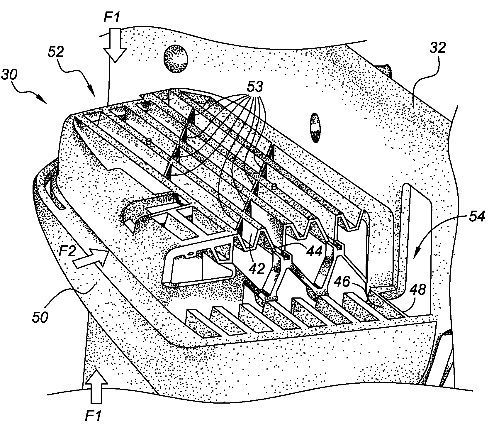
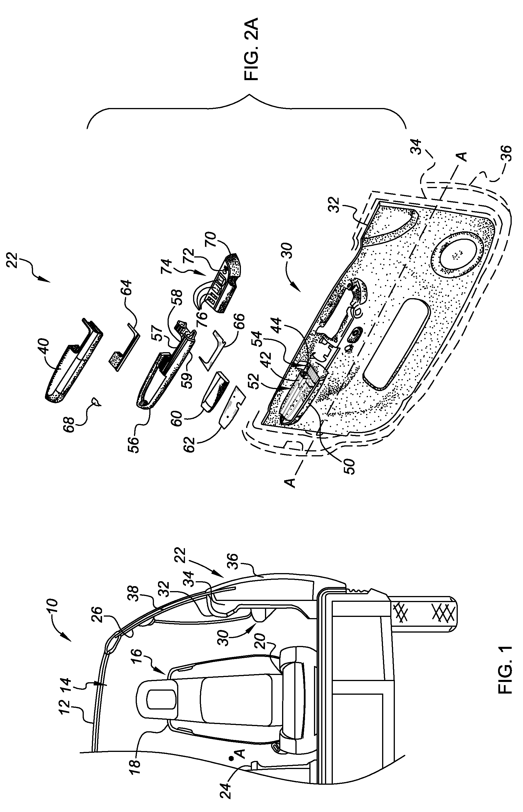
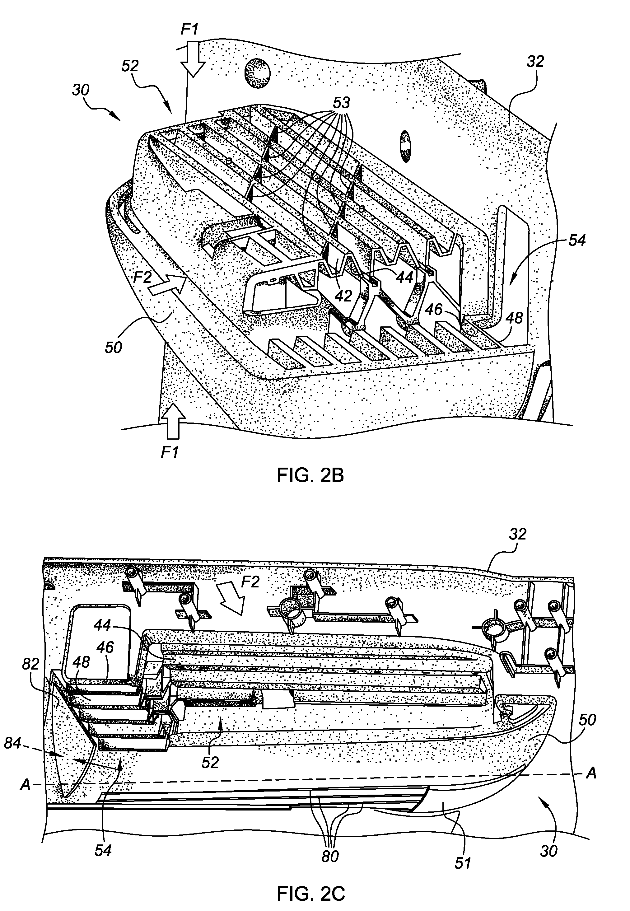
[0028]Referring to the drawings, wherein like reference numbers refer to the same or similar components throughout the several views, FIG. 1 is a front cross-sectional view of a portion of a representative motorized vehicle, identified generally as 10, with which the present invention may be practiced. The vehicle 10 has a vehicle body 12 including a vehicle interior, shown in part in FIG. 1 as passenger compartment 14, having one or more vehicle seat assemblies 16 therein. The seat assembly 16 can be of any suitable or conventional construction, but generally includes a backrest unit 18 and a lower cushion portion 20. Although the vehicle 10 is depicted in FIG. 1 as a standard coupe-type passenger car, the present invention can be incorporated into any vehicle platform, such as, but not limited to, sedan-type passenger cars, light trucks, heavy duty vehicles, minivans, buses, convertibles, etc. The vehicle body 12 has a longitudinal axis A, as best seen in FIGS. 2A and 3A, that ext...


PUM


Abstract

An armrest for use with a motorized vehicle is provided comprising first and second substantially opposing surfaces elongated longitudinally along the vehicle's interior surface and extending laterally inward therefrom. The armrest also includes a substantially vertical wall portion extending from the inner periphery of the first and second surfaces. The first and second surfaces define a plurality of channels oriented substantially parallel to one another and elongated longitudinally relative to the vehicle, in either a parallel or oblique fashion relative to a longitudinal axis of the vehicle. The plurality of channels is configured to sustain substantial vertical loading and controllably deform under a predetermined threshold lateral crush load. In addition, the plurality of channels preferably includes one or more partitions within each of the channels that are oriented relative to one another to thereby create a load path for lateral loads imparted to the armrest assembly.

Description

TECHNICAL FIELD[0001]The present invention relates generally to passenger compartments of motorized vehicles, and more specifically to armrest assemblies located in the passenger compartment that are adapted to absorb and attenuate kinetic energy imparted thereto.BACKGROUND OF THE INVENTION[0002]Most motorized vehicles include an armrest that extends from the interior surface of each vehicle door. The armrest is typically part of a decorative trim assembly on the inner panel of the door assembly, and is often integrated with a door latch release lever and / or a pull handle used to open and close the door assembly. The majority of conventional armrest assemblies are self-contained units that are adapted to be positively attached to the inner panel by, for example, fasteners or screws. The armrest is intended, in part, to provide a surface on which a vehicle occupant seated adjacent the door may rest the lower extremities of his or her arm.[0003]Armrests are often relatively rigid and ...

Claims


Application Information

Patent Timeline
Patent Type & Authority Patents(United States)
IPC IPC(8): B60N3/02B60N2/75
CPCB60N2/4235B60N2/42709B60N2/466B60R21/0428B60N2/78
Inventor THOMAS, SCOTT D.
Owner GM GLOBAL TECH OPERATIONS LLC
Learn More