
Slit-slat collimation

a collimator and slit-slat technology, applied in the field of collimator and collimator, can solve the problems of reducing the intensity (sensitivity) of the recorded image, unable to focus radiation, blurred and indistinct images so as to be useless,

Active Publication Date: 2010-11-09
THE TRUSTEES OF THE UNIV OF PENNSYLVANIA
View PDF14 Cites 50 Cited by
  • Summary
  • Abstract
  • Description
  • Claims
  • Application Information

AI Technical Summary

Benefits of technology

"The patent describes a slit-slat collimator for electromagnetic radiation that includes a frusto-pyramidal housing with a rectangular base, top, and open sides. The collimator has a plurality of axial septa and spacers that can be aligned and stacked using a means of adjustable aperture plates. The collimator can be adjusted to change the size of the collimation aperture. The technical effect of this invention is to provide a collimator that can efficiently collimate electromagnetic radiation and reduce lead shielding, making it easier to detect and analyze the radiation from a specimen."

Problems solved by technology

Collimators are used in SPECT imaging because it is currently not possible to focus radiation with such short wavelengths into an image through the use of lenses as is routine with electromagnetic radiation at optical or near-optical wavelengths.
Such an effect would occur for all parts of the specimen, resulting in an image so blurred and indistinct as to be useless.
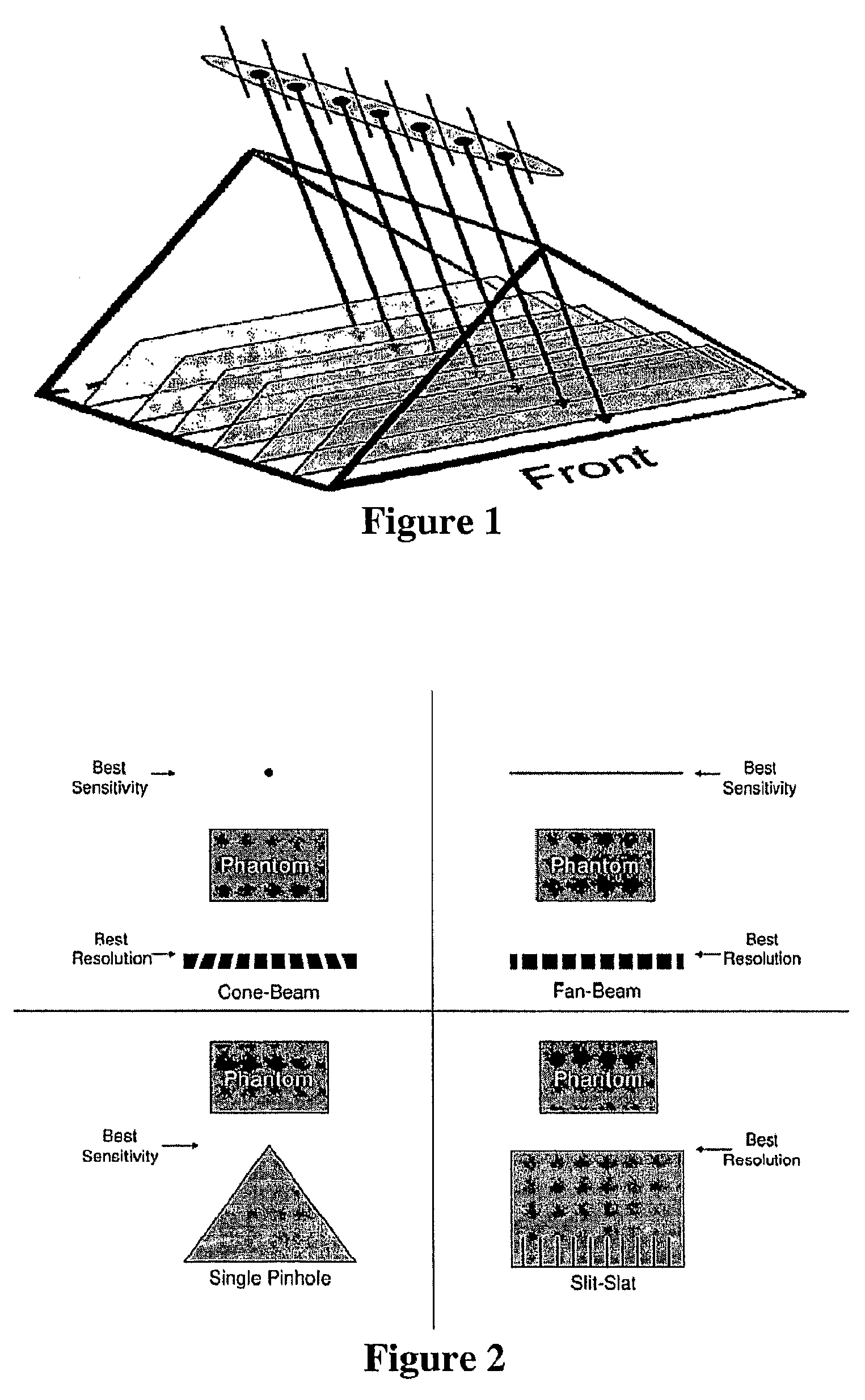
Although collimators improve the resolution of the recorded image by blocking incoming radiation that would result in a blurred image, by necessity they also reduce the intensity (sensitivity) of the recorded image.
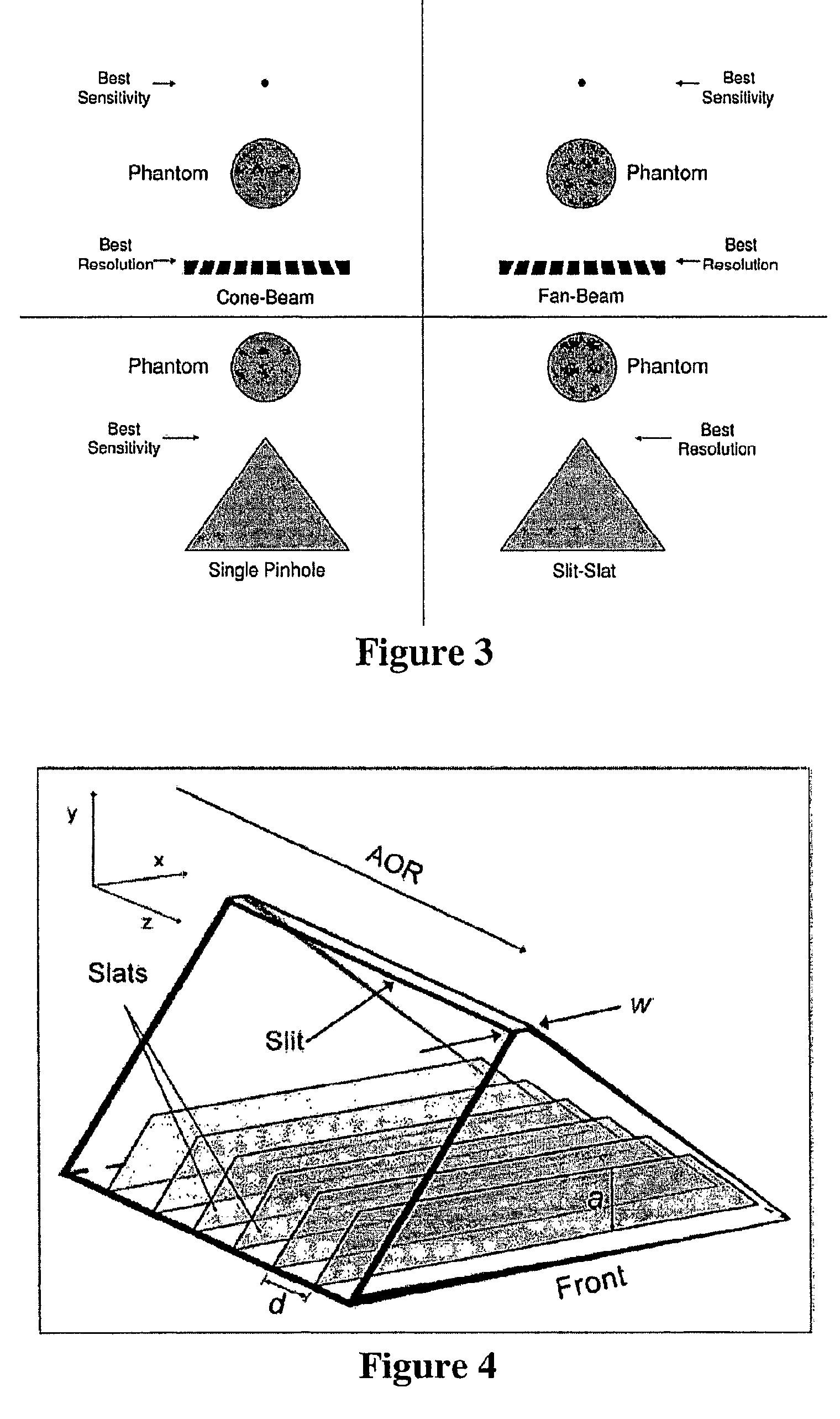
However, the magnification is smaller, resulting in worse resolution.
Although, single-pinhole collimation typically cannot offer 2D complete-sampling using a circular orbit, it has both its best resolution and sensitivity near the focal spot (aperture).

Method used


Image

  • Slit-slat collimation
  • Slit-slat collimation
  • Slit-slat collimation

Examples


example 1

Comparison of Sensitivity and Resolution for Different Collimator Types

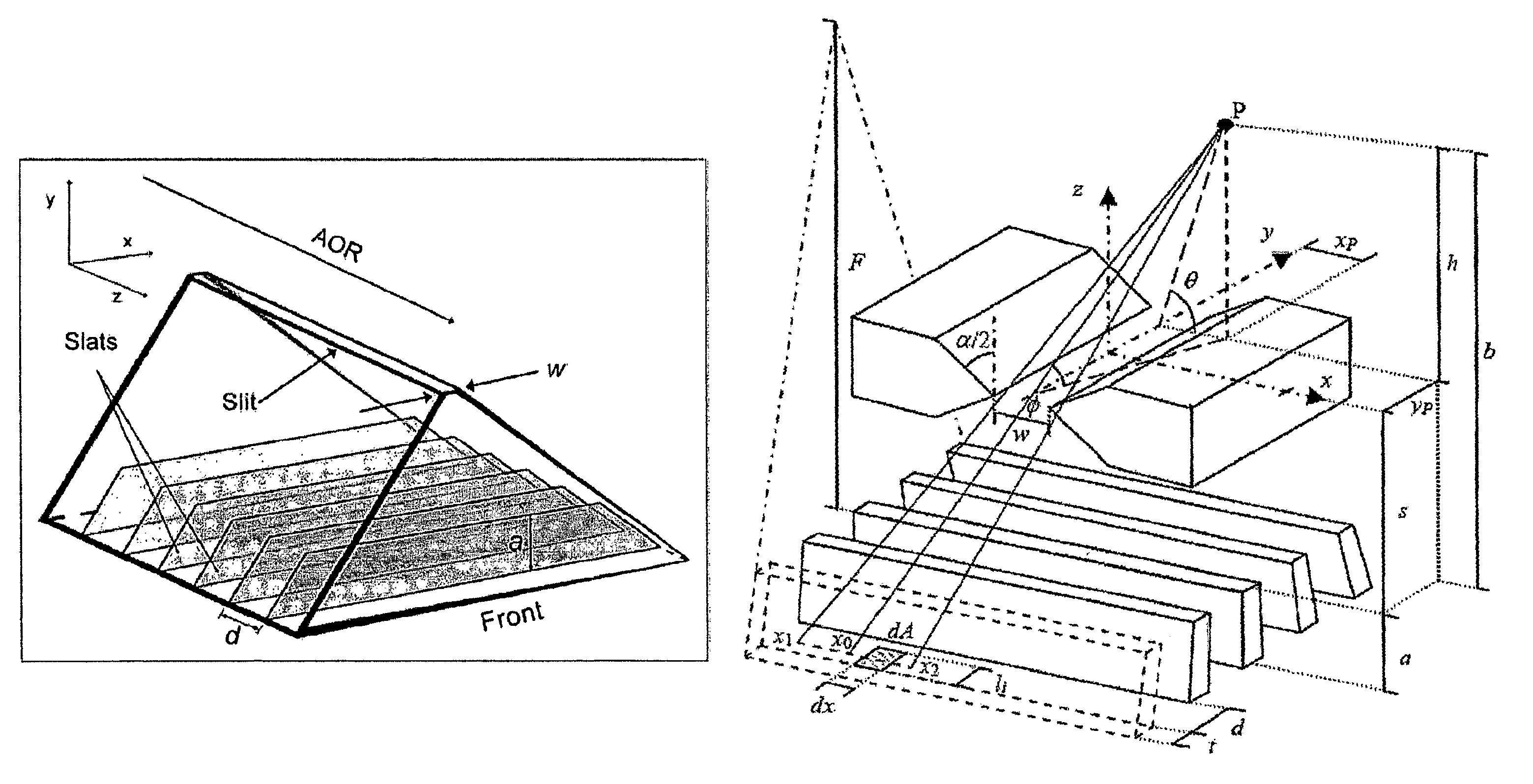
[0227]New experimental and simulated data confirming the previous hypotheses (i.e., on-axis sensitivity of slit-slat is the geometric mean of pinhole and parallel-beam; transaxial and axial resolutions are well predicted by the pinhole and parallel-beam resolution formulas, respectively) have recently been published in the Journal of Nuclear Medicine. The mathematical derivation of these results follows.

Sensitivity and Resolution Results Recently Published by the Journal of Nuclear Medicine

[0228]A simple picture of slit-slat collimation is as the combination of pinhole collimation within transaxial planes separated by septa providing collimation in 1D (the slats). The sensitivity formulas for a pinhole and a parallel-hole collimator are well established. For a pinhole, sensitivity is given by:

[0229]gp=k⁢⁢w24⁢π⁢⁢h2⁢sin3⁢θ(EQ.⁢15)

where w is the width of the pinhole (its diameter if the aperture is round), h is the ...

example 2

Single-pinhole Sensitivity

[0401]The effect of aperture penetration by high-energy photons on pinhole sensitivity has previously been investigated. Not all photons are stopped by the aperture. An analytic expression has been derived for the angle and depth dependence of the sensitivity of pinhole collimators, including the significant, often dominant, edge-penetration term. It has been found that the new analytic expression agrees well with experimental measurements of sensitivity over a range of aperture diameters, collimator materials and photon energies. Independent experimental confirmation was made by Williams et al. (Investigation of efficiency and spatial resolution using pinholes with small pinhole angle. IEEE Transactions on Nuclear Science, 2003. 50(5): p. 1562-1568). The general equation derived for pinhole sensitivity is:

[0402]Stotal≈d2⁢sin3⁢θ16⁢⁢h2+sin5⁢tan2⁢α28⁢h2⁢μ2⁢(1-cot2⁢θtan2⁢α2)1 / 2[1-cot2⁢θtan2⁢α2+μ⁢⁢d⁢⁢csc⁢⁢θ⁢⁢cot⁢⁢α2](EQ.⁢71)

wherein μ is the attenuation coeffici...

example 3

Single-Pinhole Point-Spread Function

[0406]An analytic form for the point-response function (PRF) of a pinhole aperture has been derived. The function is:

[0407]PRF={sin3⁢θ4⁢π⁡(h+b)2,r≤d⁡(h+b)2⁢hsin3⁢θ4⁢π⁡(h+b)2⁢ⅇ-μΔ⁢⁢L,r>d⁡(h+b)2⁢h(EQ.⁢73)

[0408]The multi-line equation for ΔL may be found in reference Metzler et al. equation 5 (Analytic determination of the pinhole collimator's point-spread function and RMS resolution with penetration. IEEE Transactions on Medical Imaging, 2002. 21(8): p. 878-887).

[0409]FIG. 28 shows normalized longitudinal profiles of the experimental data for a 0.77 mm-diameter, 101° opening angle tungsten aperture. A similar figure for a 4.0 mm-diameter, 84° opening angle tungsten aperture is in Metzler et al. “Pinhole collimator's point-spread function”FIG. 7. A Tc-99m line source was used for the acquisition.


PUM


Abstract

This invention is directed to a collimator and collimation techniques. Specifically, the invention is directed to a collimator and method for collimation wherein the collimator combines the resolution and sensitivity properties of pinhole Single Photon Emission Computed Tomography (SPECT) imaging with the 2D complete-sampling properties of fan-beam collimators.

Description

CROSS-REFERENCE TO RELATED APPLICATIONS[0001]This application is a National Phase Application of PCT International Application No. PCT / US07 / 06807, International Filing Date Mar. 19, 2007, claiming priority of U.S. Provisional Patent Applications, 60 / 783,077, filed Mar. 17, 2006 and US Provisional Patent Applications, 60 / 839,666, filed Aug. 24, 2006, all which are incorporated herein by reference in their entirety.FIELD OF INVENTION[0002]This invention is directed to a collimator and collimation techniques. Specifically, the invention is directed to a collimator and method for collimation wherein the collimator combines the resolution and sensitivity properties of pinhole Single Photon Emission Computed Tomography (SPECT) imaging with the 2D complete-sampling properties of fan-beam collimators.BACKGROUND OF THE INVENTION[0003]Single Photon Emission Computed Tomography (SPECT) is a nuclear-medicine imaging modality capable of providing 3D maps of in vivo radiopharmaceutical distributi...

Claims


Application Information

Patent Timeline
Patent Type & Authority Patents(United States)
IPC IPC(8): G21K1/04
CPCG01T1/1648G02B27/30
Inventor METZLER, SCOTTACCORSI, ROBERTOLEWITT, ROBERT M.
Owner THE TRUSTEES OF THE UNIV OF PENNSYLVANIA
Learn More