Coarse wavelength division multiplexing optical transmission system, and coarse wavelength division multiplexing optical transmission method

a wavelength division multiplexing and optical transmission technology, applied in multiplex communication, instruments, optical elements, etc., can solve the problems of high cost of dwdm system, and inability to consider the method of transmitting connected optical signals for dwdm system over optical fiber, so as to avoid the effect of reducing transmission quality

Active Publication Date: 2010-11-09
FUJITSU LTD
View PDF12 Cites 11 Cited by
  • Summary
  • Abstract
  • Description
  • Claims
  • Application Information

AI Technical Summary

Benefits of technology

[0012]The present invention has been accomplished in view of the above problem and has an object of providing a CWDM optical transmission system and a CWDM optical transmission method, capable of realizing at low-cost an increase of the number of optical signals in a CWDM system by utilizing an optical transmission apparatus used in a DWDM system, and at the same time, avoiding the reduction in transmission quality.
[0017]According to the above described CWDM optical transmission system of the present invention, the addition of optical signals in the CWDM system can be realized at a low-cost utilizing an optical transmission apparatus used in the DWDM system, while avoiding the reduction in transmission quality due to the nonlinear effect in the transmission path. As a result, it becomes possible to add the optical signals so as to exceed the maximum number of signals in the CWDM system.

Problems solved by technology

This DWDM system can normally be operated with a number of signals of between 32 and 128 waves, however, in order to accurately manage wavelengths, requires expensive light source and wavelength management equipment.
Therefore, the cost of the DWDM system is high even when operated with a small number of signals.
However, in the above described conventional technology, only the method of connecting optical signals for the DWDM system to the CWDM system has been considered, and the method of transmitting the connected optical signals for the DWDM system over the optical fiber has not been considered.
Therefore, an effective optical fiber transmission has been difficult.
That is to say, in the case where optical signals of a plurality of wavelengths operated in the DWDM system are connected directly to the CWDM system while the setting of the power, the inter-wavelength or the like thereof being unchanged, and the number of signals in the CWDM system are added, such a problem is considered in that the waveform deterioration due to a nonlinear effect of the optical fiber or an increase of noise and the like due to cross-talk caused by a characteristic of an optical multiplexer / demultiplexer for the CWDM system occurs in the added optical signal of the DWDM side, resulting in the reduction in transmission quality.

Method used


Image

  • Coarse wavelength division multiplexing optical transmission system, and coarse wavelength division multiplexing optical transmission method
  • Coarse wavelength division multiplexing optical transmission system, and coarse wavelength division multiplexing optical transmission method
  • Coarse wavelength division multiplexing optical transmission system, and coarse wavelength division multiplexing optical transmission method

Examples


first embodiment

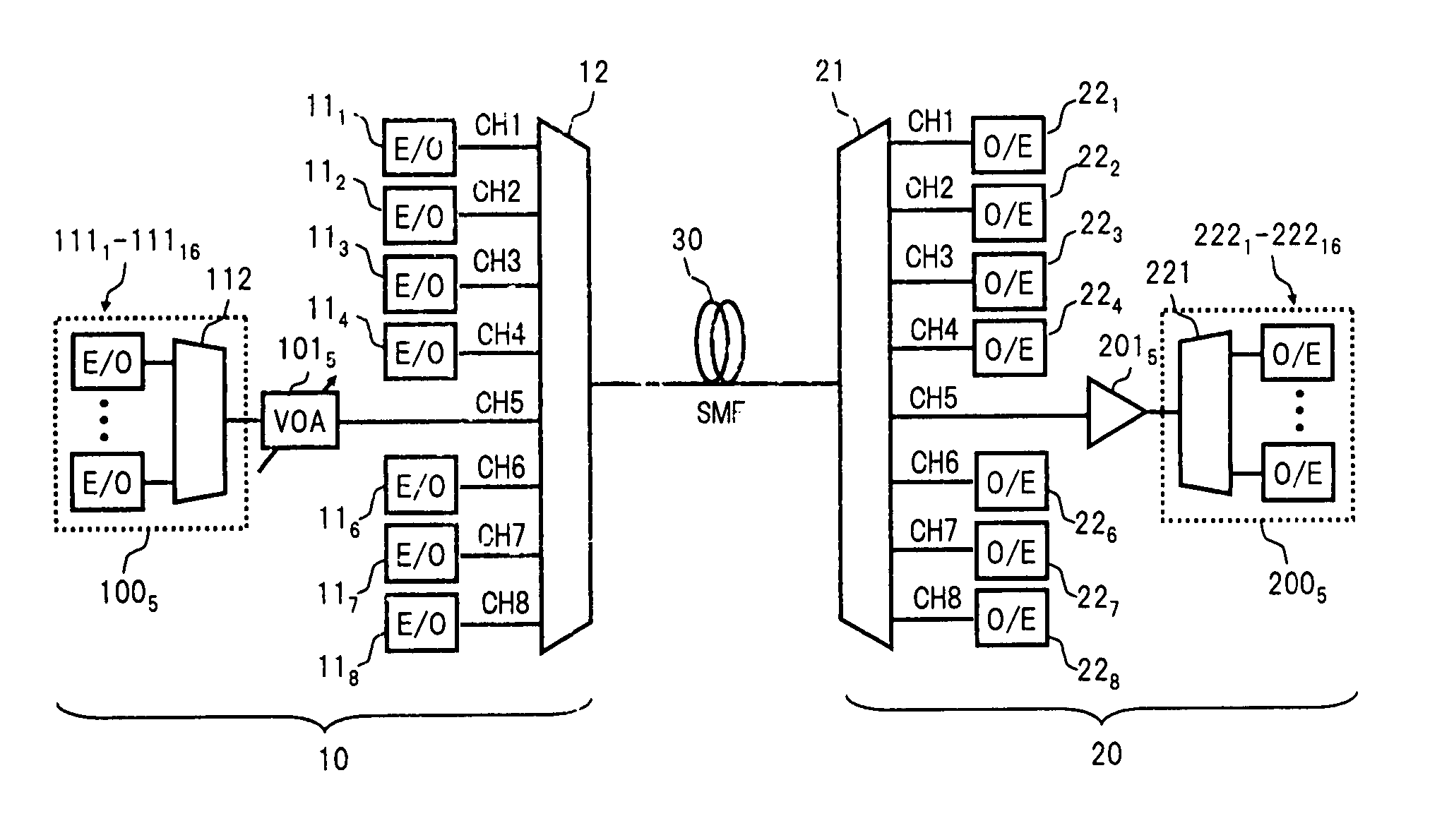
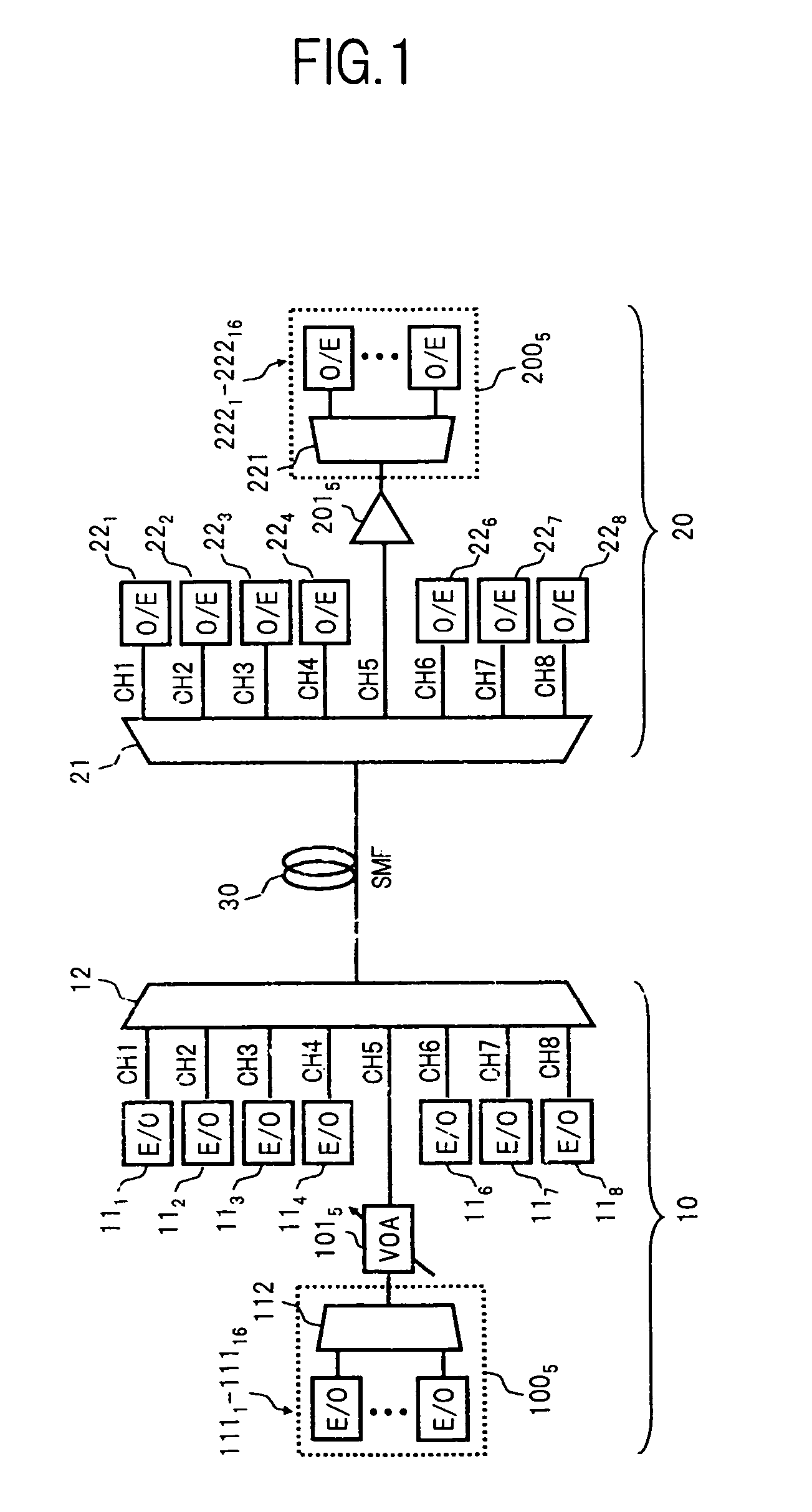
[0044]FIG. 1 is a diagram showing a configuration of a CWDM optical transmission system according to the present invention.

[0045]In FIG. 1, the CWDM optical transmission system of the present embodiment comprises, for example, an optical transmission terminal 10, and an optical reception terminal 20 connected to the optical transmission terminal 10 via a transmission path 30.

[0046]The optical transmission terminal 10 includes: for example, optical transmitters (E / O) 111 through 114, and 116 through 118 generating optical signals CH1 through CH4, and CH6 through CH8 among a plurality (8 waves in this case) of optical signals CH1 through CH8 arranged on a wavelength grid having 20 nm inter-wavelength corresponding to CWDM; a multiplexer 12 having 8 input ports corresponding to the optical signals CH1 through CH8 and one output port; an additional light transmission unit 1005 which generates a DWDM light as an additional light in place of the optical signal CH5; and a variable optical ...

second embodiment

[0073]Next, the present invention will be described.

[0074]FIG. 5 is a diagram showing a configuration of a CWDM optical transmission system of the second embodiment.

[0075]The CWDM optical transmission system shown in FIG. 5 is configured such that, in the configuration of the first embodiment, in addition to the wavelength of the optical signal CH5, the wavelength of the optical signal CH7 is set as the additional wavelength, and the L-band optical transmission apparatus used in the existing DWDM system is also utilized to increase the number of signals capable to be added. More specifically, an additional light transmission unit 1007 and a variable optical attenuator 1017 are provided in the optical transmission terminal 10, in place of the optical transmitter 117 used in the first embodiment, and the power of a DWDM light output from the additional light transmission unit 1007 is adjusted by the variable optical attenuator 1017 and thereafter, given to the input port, which corres...

third embodiment

[0079]Next, the present invention will be described.

[0080]FIG. 7 is a diagram showing a configuration of a CWDM optical transmission system of the third embodiment.

[0081]The CWDM optical transmission system shown in FIG. 7 is configured such that, in the configuration of the second embodiment, in addition to the wavelengths of the optical signals CH5 and CH7, the wavelengths of the optical signals CH4 and CH6 are also set as the additional wavelengths, and the C-band and L-band optical transmission apparatuses used in the existing DWDM system are also utilized to further increase the number of signals capable to be added.

[0082]More specifically, in the optical transmission terminal 10, there is provided; an additional light transmission unit 10045 which generates a DWDM light as the additional light in place of the optical signals CH4 and CH5, a variable optical attenuator 10145 which adjusts the total power of the DWDM light, and a demultiplexer 10245 which demultiplexes the DWDM l...


PUM


Abstract

In a CWDM optical transmission system of the present invention, in place of an optical signal of at least one wave among a plurality of optical signals corresponding to a CWDM system, a DWDM light output from an additional light transmission unit of a DWDM system is given to a multiplexer via a variable optical attenuator, and multiplexed with the optical signals corresponding to CWDM, to be sent out to a transmission path. At this time, the total power of the DWDM light sent out to the transmission path, is attenuated by the variable optical attenuator, so as to be approximately equal to the power per one wavelength of the CWDM light. On an optical reception terminal, the light propagated through the transmission path is demultiplexed by a demultiplexer, and the DWDM light corresponding to the additional wavelengths is amplified by an optical amplifier and thereafter, received by an additional light reception unit. As a result, the addition of optical signals in the CWDM system can be realized at low-cost, while avoiding the reduction in transmission quality.

Description

[0001]The present application is a continuation-in-part of U.S. patent application Ser. No. 10 / 895,325, filed Jul. 21, 2004 now abandoned, the complete disclosure of which is incorporated herein by reference in its entirely.BACKGROUND OF THE INVENTION[0002](1) Field of the Invention[0003]The present invention relates to an optical transmission system and an optical transmission method, for transmitting a wavelength division multiplexed light containing a plurality of optical signals of different wavelengths, by the use of an optical fiber, and in particular, relates to technology for adding optical signals in a coarse wavelength division multiplexing system.[0004](2) Related Art[0005]A dense wavelength division multiplexing (hereafter referred to as DWDM) system, which deals with a plurality of optical signals of 0.8 nm inter-wavelength and further at 0.4 nm, has been developed, and is now in practical use, as a communication system enabling a dramatic increase in transmission capac...

Claims


Application Information

Patent Timeline
Patent Type & Authority Patents(United States)
IPC IPC(8): G02B6/28H04J14/02H04B10/00H04B10/2507H04J14/00
CPCH04J14/02H04J14/0221H04J14/0224H04J14/00H04B10/2581H04B10/25
Inventor OIKAWA, YOICHITOYOMAKI, TAKASHIOHTSUKA, TOMOYUKI
Owner FUJITSU LTD
Why Eureka
Try Eureka