
Spinal implants with body and insert

a technology of spine and body, applied in the field of spine implants, can solve the problems of destabilizing the spinal column, altering the natural separation distance between adjacent vertebrae, pain and/or nerve damage, etc., and achieve the effect of promoting the fusion of adjacent vertebra

Active Publication Date: 2010-11-16
ZIMMER BIOMET SPINE INC
View PDF12 Cites 53 Cited by
  • Summary
  • Abstract
  • Description
  • Claims
  • Application Information

AI Technical Summary

Benefits of technology

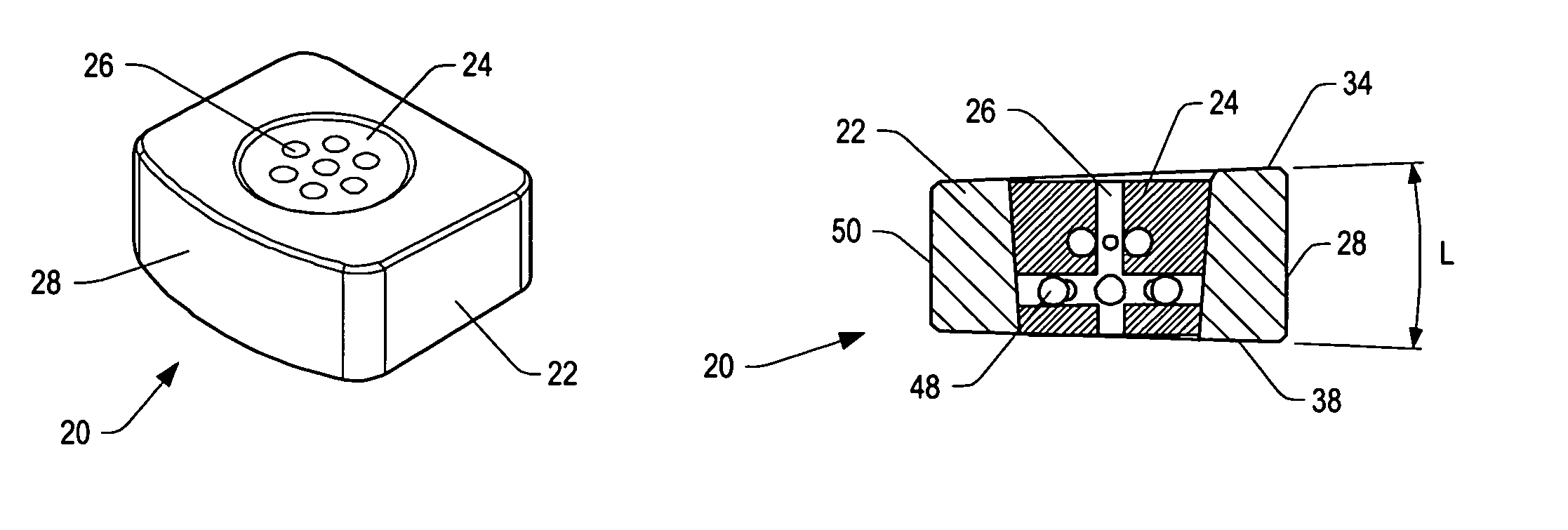
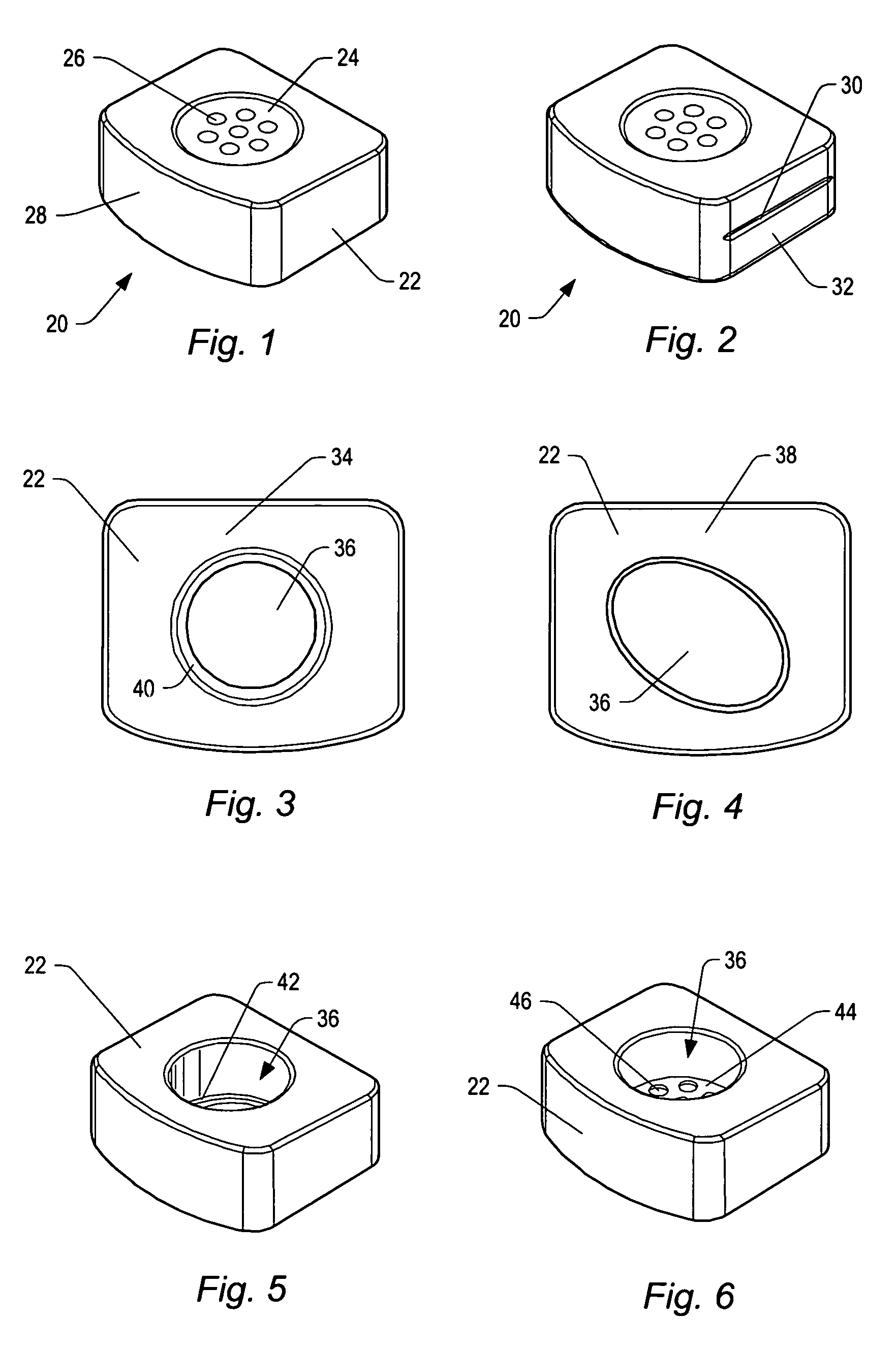
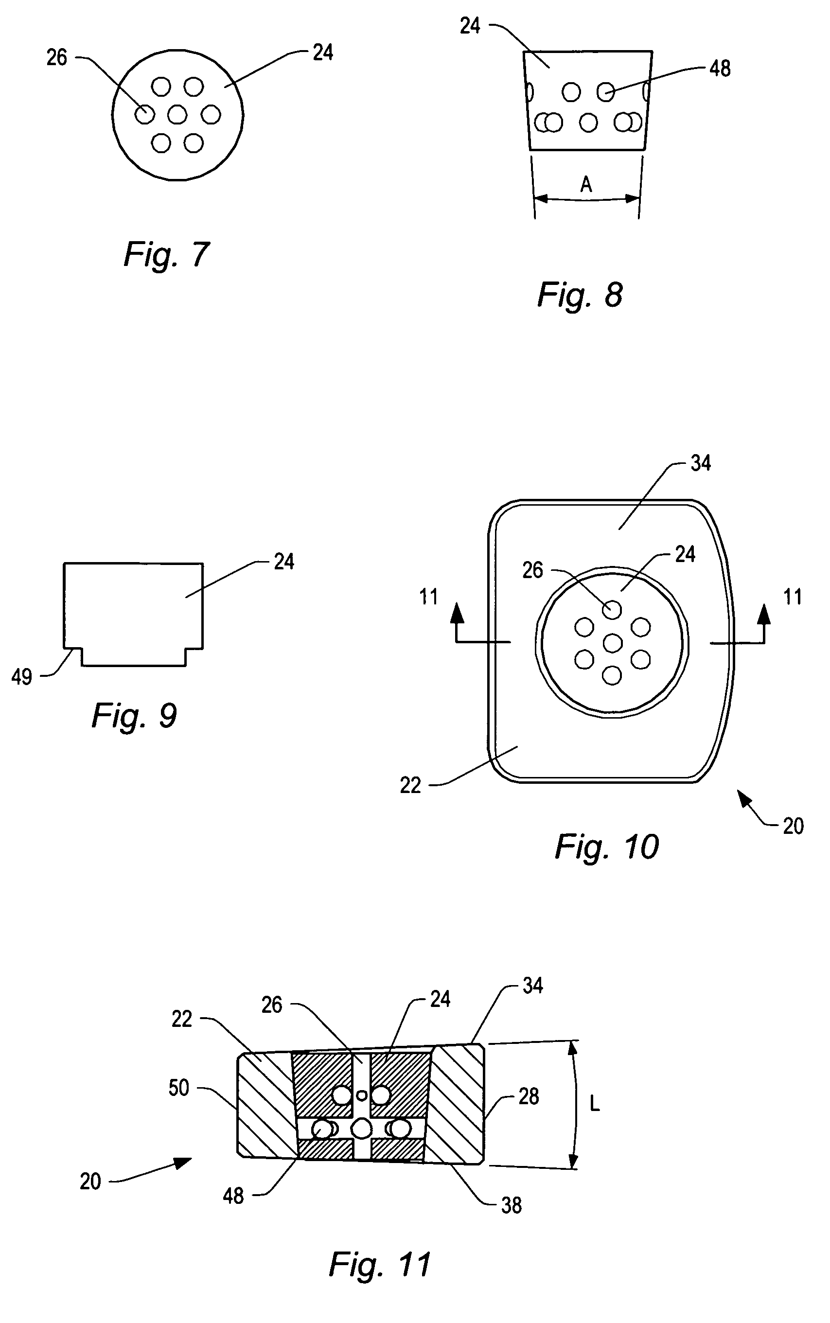
"The patent describes a spinal implant that can be used to promote bone growth and fusion between adjacent vertebrae. The implant consists of a body and an insert. The body is made of a ceramic material and has an ultimate compressive strength that is comparable to the strength of a cortical allograft spacer. The body has a mechanical crush resistance that is greater than the insert. The insert is made of a ceramic material and has passageways that facilitate bone ingrowth. The implant can be inserted during a spinal fusion procedure and can be shaped to conform to the shape of the vertebrae. The patent also describes the use of bone growth promoting material in the passageways of the implant to promote bone growth. The technical effects of the spinal implant include improved spinal fusion and stability, reduced complications, and improved patient outcomes."

Problems solved by technology

Partial or full removal of an intervertebral disc may destabilize the spinal column.
Destabilization of a spinal column may result in alteration of a natural separation distance between adjacent vertebrae.
Excessive pressure applied to the nerves may cause pain and / or nerve damage.
Spinal surgery may be complex due in part to the proximity of delicate soft tissue such as the spinal cord, cauda equina, and / or vascular structures.

Method used


Image

  • Spinal implants with body and insert
  • Spinal implants with body and insert
  • Spinal implants with body and insert

Examples


Embodiment Construction

[0034]A spinal implant may be used during the treatment of trauma, disease, and / or neoplasia. A spinal implant may establish a separation distance between adjacent vertebrae. A spinal implant may fill a defect in a single vertebra. The spinal implant may promote bone growth between the adjacent vertebrae. The bone growth may fuse the vertebrae together. The spinal implant may establish a desired angle between the vertebrae. In some spinal implant embodiments, a surface of the spinal implant that will contact a vertebra, or both surfaces of the spinal implant that will contact the vertebrae, may be tapered so that the spinal implant has a desired angle. A cervical or lumbar spinal implant may have an anterior height that is larger than a posterior height to establish a desired amount of lordosis. A cervical spinal implant may have from about 0° to about 12° of lordotic angle. Some cervical spinal implants may have from about 0° to about 6° of lordotic angle, or from about 3° to about...


PUM


Abstract

A spinal implant is provided which maintains intervertebral spacing and stability within the spine. The spinal implant may include a body and an insert. The body of the spinal implant may be formed of a ceramic material. In some embodiments, the body may be formed of beta tricalcium phosphate. The body may include an opening that is complementary to the insert. The insert may fit within the opening. The insert may include a number of passageways. Some of the passageways may intersect to form a scaffold for bone growth. Bone growth promoting material may be introduced into the insert before the insert is positioned in a body and inserted in a patient between two vertebrae.

Description

BACKGROUND[0001]1. Field of the Invention[0002]The present invention generally relates to spinal implants. More particularly, certain embodiments of this invention relate to ceramic implants having supportive bodies and bone growth promoting inserts.[0003]2. Description of Related Art[0004]An intervertebral disc may degenerate. Degeneration may be caused by trauma, disease, and / or aging. An intervertebral disc that becomes degenerated may have to be partially or fully removed from a spinal column. Partial or full removal of an intervertebral disc may destabilize the spinal column. Destabilization of a spinal column may result in alteration of a natural separation distance between adjacent vertebrae. Maintaining the natural separation distance between vertebrae may prevent pressure from being applied to nerves that pass between vertebral bodies. Excessive pressure applied to the nerves may cause pain and / or nerve damage. During a spinal fixation procedure, a spinal implant may be ins...

Claims


Application Information

Patent Timeline
Patent Type & Authority Patents(United States)
IPC IPC(8): A61F2/44A61F2/00A61F2/28A61F2/30A61F2/46
CPCA61F2/4465A61F2/447A61F2/4611A61F2002/2817A61F2002/2835A61F2002/30187A61F2002/302A61F2002/30266A61F2002/30331A61F2002/30332A61F2002/30487A61F2002/30784A61F2002/30795A61F2002/3082A61F2002/30909A61F2220/0025A61F2220/0033A61F2230/0034A61F2230/0065A61F2230/0082A61F2310/00293
Inventor MITCHELL, MARGARET E.FREID, JIM
Owner ZIMMER BIOMET SPINE INC
Learn More