
Pulse width modulation output type sensor circuit for outputting a pulse having a width associated with a physical quantity

a sensor circuit and pulse width technology, applied in the field of pulse width modulation output sensor circuits, can solve the problems of reducing a dynamic range, poor accuracy of digital data outputted from a/d converters, and pressure sensors that may not accurately detect pressure, so as to achieve accurate detection of physical quantities and variable resolution

Inactive Publication Date: 2010-11-16
DENSO CORP
View PDF13 Cites 3 Cited by
  • Summary
  • Abstract
  • Description
  • Claims
  • Application Information

AI Technical Summary

Benefits of technology

The present invention provides a sensor circuit that can accurately detect a physical quantity over a wide range and have a variable resolution. The circuit includes a physical quantity obtaining circuit, a sampling number determination circuit, a sampling circuit, a calculation circuit, a pulse width modulation conversion circuit, and an output circuit. The sensor circuit can sample the sensor signal multiple times and calculate the average value to generate a pulse width modulation signal, which can be output through the output circuit. This allows for more accurate and precise detection of physical quantities.

Problems solved by technology

As a result, the digital data outputted from A / D converter is poor in accuracy, and the pressure sensor may not accurately detect pressure.
However, the increase in resolution result in a reduction in a dynamic range, and such a high-performance A / D converter and PWM conversion circuit are costly.
Therefore, although there is often a requirement to change the resolution according to the detected pressure, the pressure sensor cannot satisfy the requirement.

Method used


Image

  • Pulse width modulation output type sensor circuit for outputting a pulse having a width associated with a physical quantity
  • Pulse width modulation output type sensor circuit for outputting a pulse having a width associated with a physical quantity
  • Pulse width modulation output type sensor circuit for outputting a pulse having a width associated with a physical quantity

Examples


Embodiment Construction

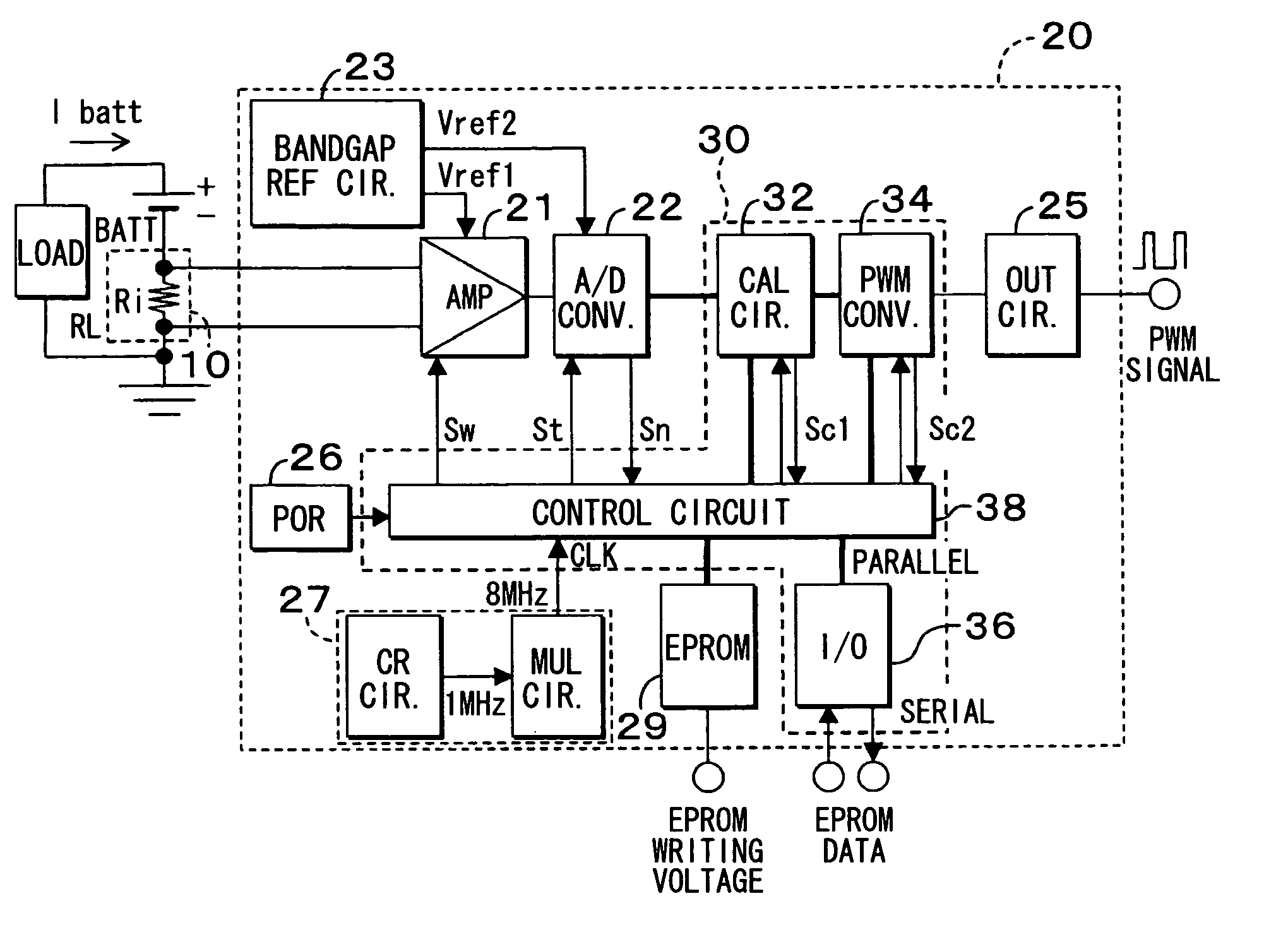
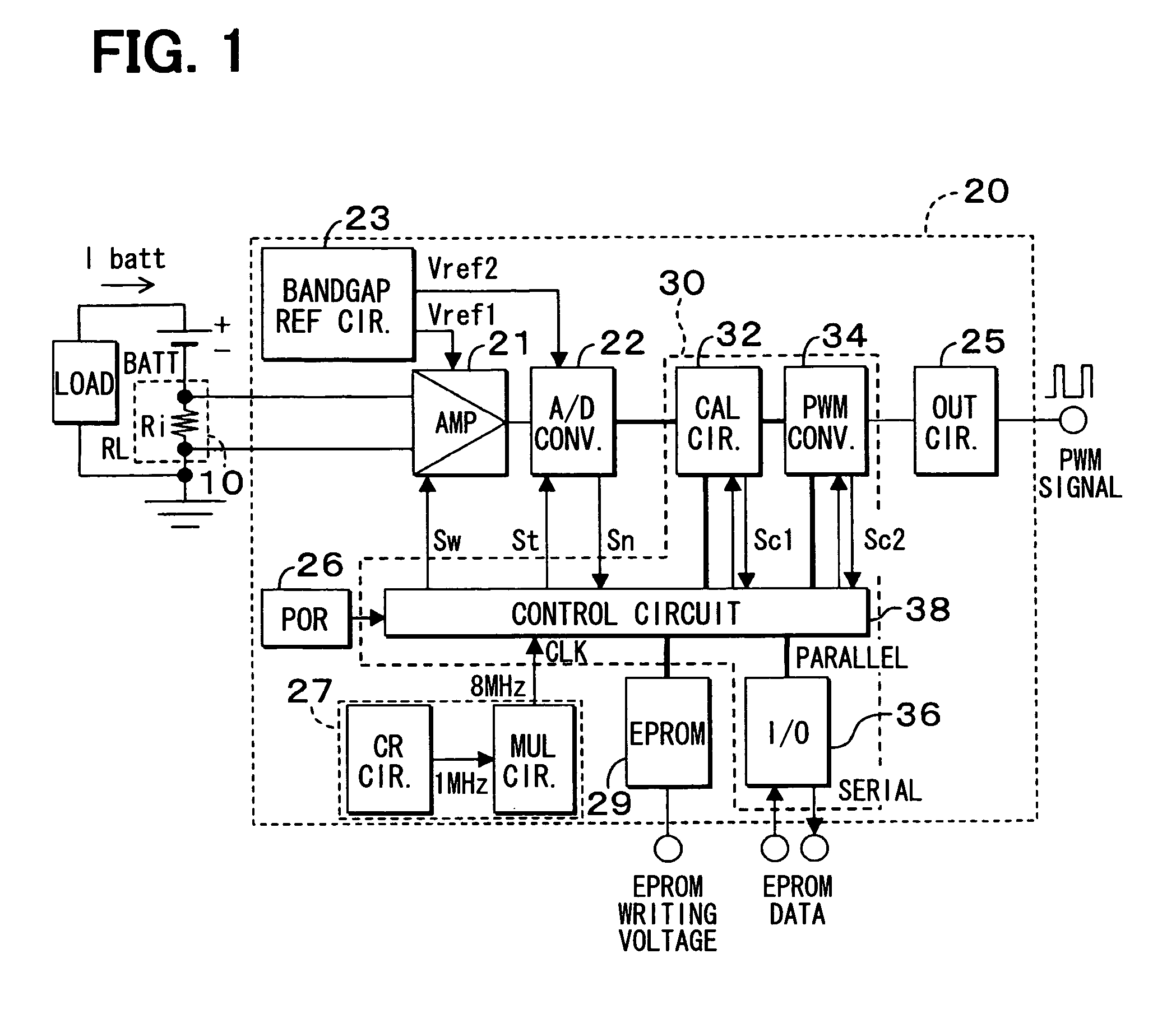
[0016]Referring to FIG. 1, a pulse width modulation (PWM) output type sensor circuit 20 according to an embodiment of the present invention includes an amplifier (AMP) 21, an analog-to-digital (A / D) converter 22, a constant voltage circuit 23, an output circuit 25, a power-on reset (POR) circuit 26, a clock generation circuit 27, an erasable programmable read only memory (EPROM) 29, and a digital signal processor (DSP) 30. The sensor circuit 20 is used to measure a battery current Ibatt of a vehicle battery BATT. The sensor circuit 20 produces a pulse-width modulation (PWM) signal having a pulse width associated with magnitude of the battery current Ibatt detected by a sensing element 10.

[0017]In the present embodiment, the battery current Ibatt flows through on-board electrical equipments (i.e., electrical loads) such as an engine starter motor, a power steering assist motor, a headlamp, and the like, and the sensing element 10 includes a resistor Ri coupled in series with the batt...


PUM


Abstract

A sensor circuit includes an analog-to-digital converter, a control circuit, a calculation circuit, and a pulse width modulation converter. The analog-to-digital converter converts an electric signal associated with a detected physical quantity to sensor data by sampling the electric signal a predetermined sampling number times per a predetermined sampling section. The control circuit determines the sampling number based on a magnitude of the electric signal. The calculation circuit calculates an average value of all the sensor data per the sampling section. The pulse width modulation converter generates a pulse width modulation signal having a pulse width corresponding to the average value.

Description

CROSS REFERENCE TO RELATED APPLICATION[0001]This application is based on and incorporates herein by reference Japanese Patent Application No. 2007-14125 filed on Jan. 24, 2007.FIELD OF THE INVENTION[0002]The present invention relates to a sensor circuit for generating a pulse width modulation signal having a pulse width associated with a detected physical quantity.BACKGROUND OF THE INVENTION[0003]A pulse width modulation (PWM) output type pressure sensor disclosed in JP-A-H11-237290 produces a PWM output having a pulse width associated with detected pressure. In the pressure sensor, an analog voltage outputted from a sensing element is converted to a 10-bit digital signal by an analog-to-digital (A / D) converter, and a PWM conversion circuit generates a PWM signal having a duty ratio varying from 2 percents (%) to 95% according to the digital signal. The PWM signal is outputted through an output circuit.[0004]An A / D conversion time of the A / D converter must meet a requirement that a ...

Claims


Application Information

Patent Timeline
Patent Type & Authority Patents(United States)
IPC IPC(8): H01L31/00
CPCG01D5/246
Inventor TANIZAWA, YUKIHIKO
Owner DENSO CORP
Learn More