Luminous structure comprising at least one light-emitting diode, its manufacture and its applications

Inactive Publication Date: 2010-11-16
SAINT-GOBAIN GLASS FRANCE
View PDF2 Cites 248 Cited by
  • Summary
  • Abstract
  • Description
  • Claims
  • Application Information

AI Technical Summary

Benefits of technology

[0012]The aim of the present invention is to provide a luminous structure having one or more light-emitting diodes—with direct illumina

Problems solved by technology

The Applicant has found that these luminous structures of the prior art have at least one of the following drawbacks:lack of compactness, especially a size problem;design complexity (number and shape of the parts, number of manufacturing steps, production difficulties);ri

Method used


Image

  • Luminous structure comprising at least one light-emitting diode, its manufacture and its applications
  • Luminous structure comprising at least one light-emitting diode, its manufacture and its applications
  • Luminous structure comprising at least one light-emitting diode, its manufacture and its applications

Examples


first embodiment

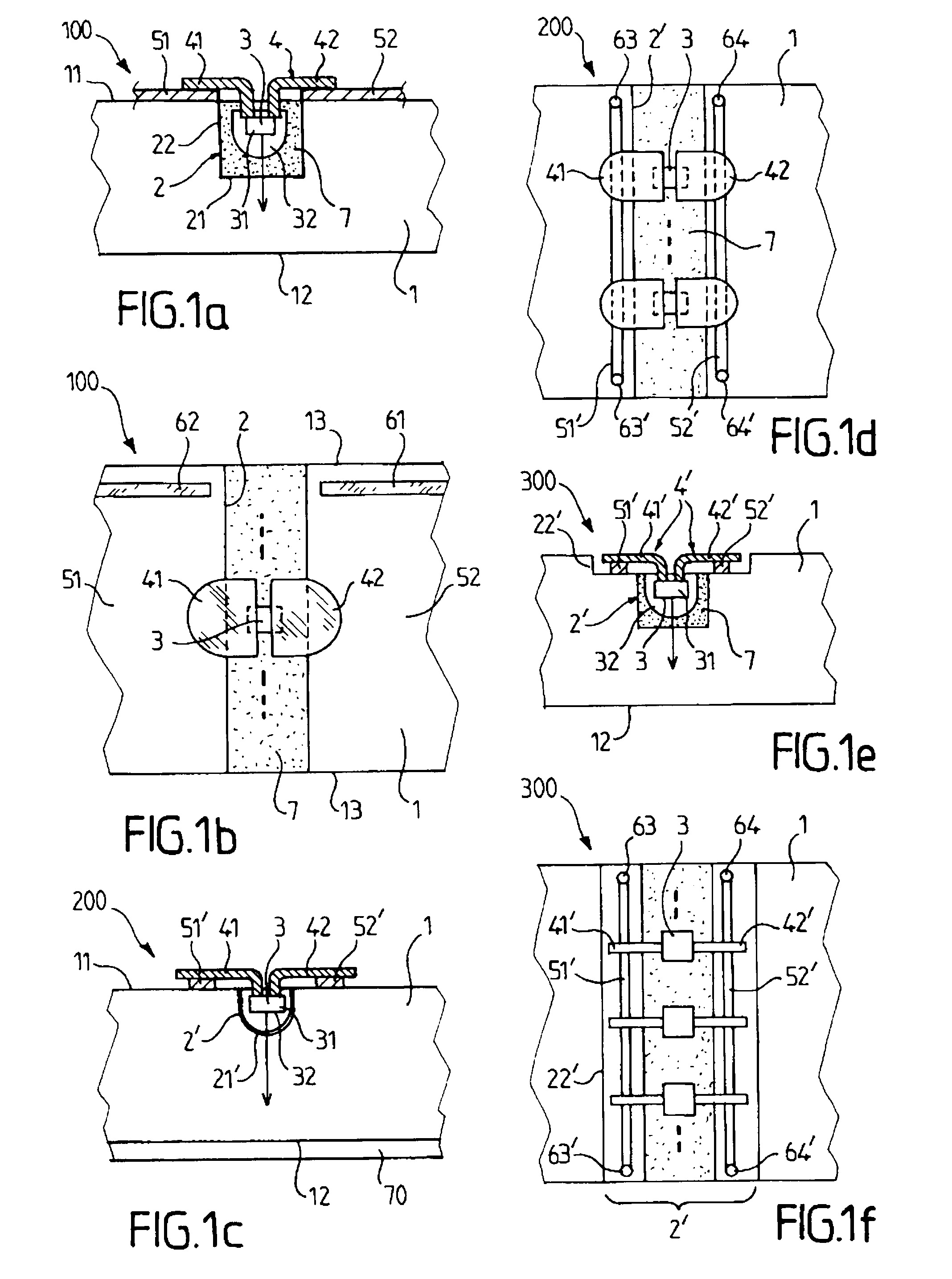
[0211]FIGS. 1a and 1b show respectively a schematic, partial sectional view and a schematic, partial top view of a luminous structure 100 with a diode in the invention.

[0212]This luminous structure 100 comprises a planar, for example parallelepipedal, mineral dielectric element, preferably a sheet 1 made of glass having a very low absorption for monochromatic radiation in the visible or even for radiation having several wavelengths in the visible. Thus, a glass with a linear absorption coefficient in the visible of 1.8 10−3 mm−1 or less is preferred. Thus, an extra-clear soda-lime glass, for example an ALBARINO glass from Saint-Gobain, with a thickness of 4 or 6 mm may be chosen.

[0213]The sheet 1 has first and second parallel main faces 11, 12 and an edge (not visible).

[0214]This structure 100 preferably emits direct illumination via the second face 12 by means of diodes 3, the main emission direction (shown symbolically by the arrow) of which is perpendicular to the face of the sem...

second embodiment

[0241]FIGS. 1c and 1d show respectively a schematic, partial sectional view and a schematic, partial top view of a luminous structure 200 having a diode in the invention.

[0242]This luminous structure 200 differs from the structure 100 in the following manner:[0243]the groove 2′ has a concave bottom 21′;[0244]the diodes are bonded in the groove with a suitable adhesive, for example limiting the reflection;[0245]the electrodes 51′, 52′ are ink jet tracks with metal, for example silver or copper, (nano)particles, with a width for example of 0.2 mm;[0246]the busbars are replaced with copper electrical wires (not visible) connected via peripheral spots of solder 63 to 64′; and[0247]the face 12 comprises a diffusing mineral layer 70.

[0248]Furthermore, the metal parts 41, 42 may thus also be in direct contact (by being folded, longer or suitably mounted) with the glass pane 1.

[0249]Moreover, these ink jet tracks may be sufficiently adhesive to fasten the metal parts 41, 42.

third embodiment

[0250]FIGS. 1e and 1f show respectively a schematic, partial sectional view and a schematic, partial top view of a luminous structure 300 with a diode in the invention.

[0251]This luminous structure 300 differs from the structure 200 in the following manner:[0252]the groove 2′ comprises a bore 22′ receiving the metal parts 41′, 42′, and therefore not extending beyond the groove;[0253]the metal parts 41′, 42′ are of smaller contact area, for example a rectangular and nonrounded area, which is suitable for a decorative application;[0254]the electrodes 51′, 52′ and the spots of solder 63 to 64′ are also in the bore 22; and[0255]the groove 2′ has partly a rectangular cross section, with a flat bottom.

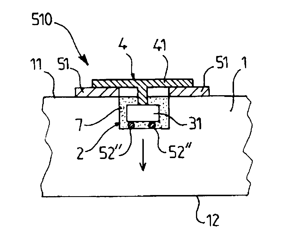
[0256]FIG. 1g shows a schematic, partial sectional view of a luminous structure 110 with diodes in a variant of the first embodiment of the invention.

[0257]This luminous structure 110 differs from the structure 100 in the following manner: the diodes 3′ are side-emitting diodes and in an inv...


PUM

PropertyMeasurementUnit
Thicknessaaaaaaaaaa
Widthaaaaaaaaaa
Coloraaaaaaaaaa

Abstract

A luminous structure includes at least one light-emitting diode emitting radiation within the ultraviolet or the visible spectrum, a substantially planar glass element having main faces and an edge around a periphery of the main faces. The glass element includes a hole housing the diode, and a metallic element connected to the diode and coupled with said glass element for removing heat. The metallic element is chosen from an electrical connection element or a holding element for keeping the diode in said hole. The invention also relates to the manufacture of this luminous structure and to its applications.

Description

BACKGROUND OF THE INVENTION[0001]I. Field of the Invention[0002]The present invention relates to a luminous structure and in particular to a luminous structure comprising at least a first light-emitting diode, to the process for manufacturing this structure and to its applications.[0003]II. Description of Related Art[0004]Various illuminating planar structures incorporating a plurality of light-emitting diodes (LEDs) exist.[0005]Firstly, luminous structures with direct illumination are known. In a first known configuration, the light-emitting diodes are placed on a main face of a monolithic planar glass pane having transparent electrodes, the electrodes being connected to the electrical contacts of the diodes by soldered wires. In a second known configuration, the diodes are assembled on a plastic printed circuit board (PCB) which is inserted into a laminated glass pane.[0006]Also known are luminous structures with illumination via the edge. They comprise a plurality of light-emitti...

Claims


Application Information

Patent Timeline
IPC IPC(8): H01J1/62H01L33/48H01L33/54H01L33/60H01L33/62H01L33/64
CPCB32B17/10036B32B17/10761G02B6/0091G02B6/0021Y10T29/49002G02B6/0085B32B17/10541G02B6/00G02B6/42
Inventor JOUSSE, DIDIERNUGUE, JEAN-CLEMENT
Owner SAINT-GOBAIN GLASS FRANCE
Why Eureka
Try Eureka