
Dynamic path protection in an optical network

a dynamic path and optical network technology, applied in the field of communication networks, can solve the problems of slow ip convergence and failure of routing adjacencies

Active Publication Date: 2010-11-16
CISCO TECH INC
View PDF18 Cites 23 Cited by
  • Summary
  • Abstract
  • Description
  • Claims
  • Application Information

AI Technical Summary

Benefits of technology

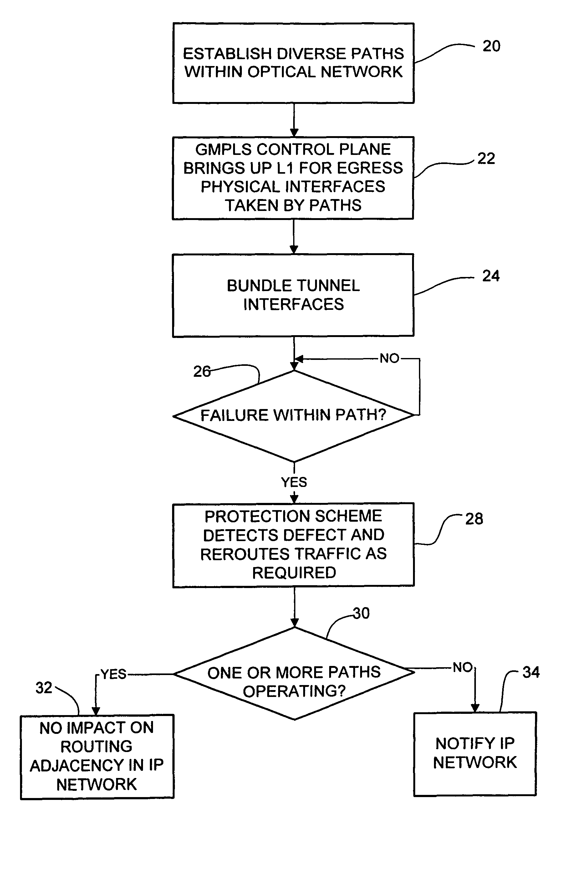
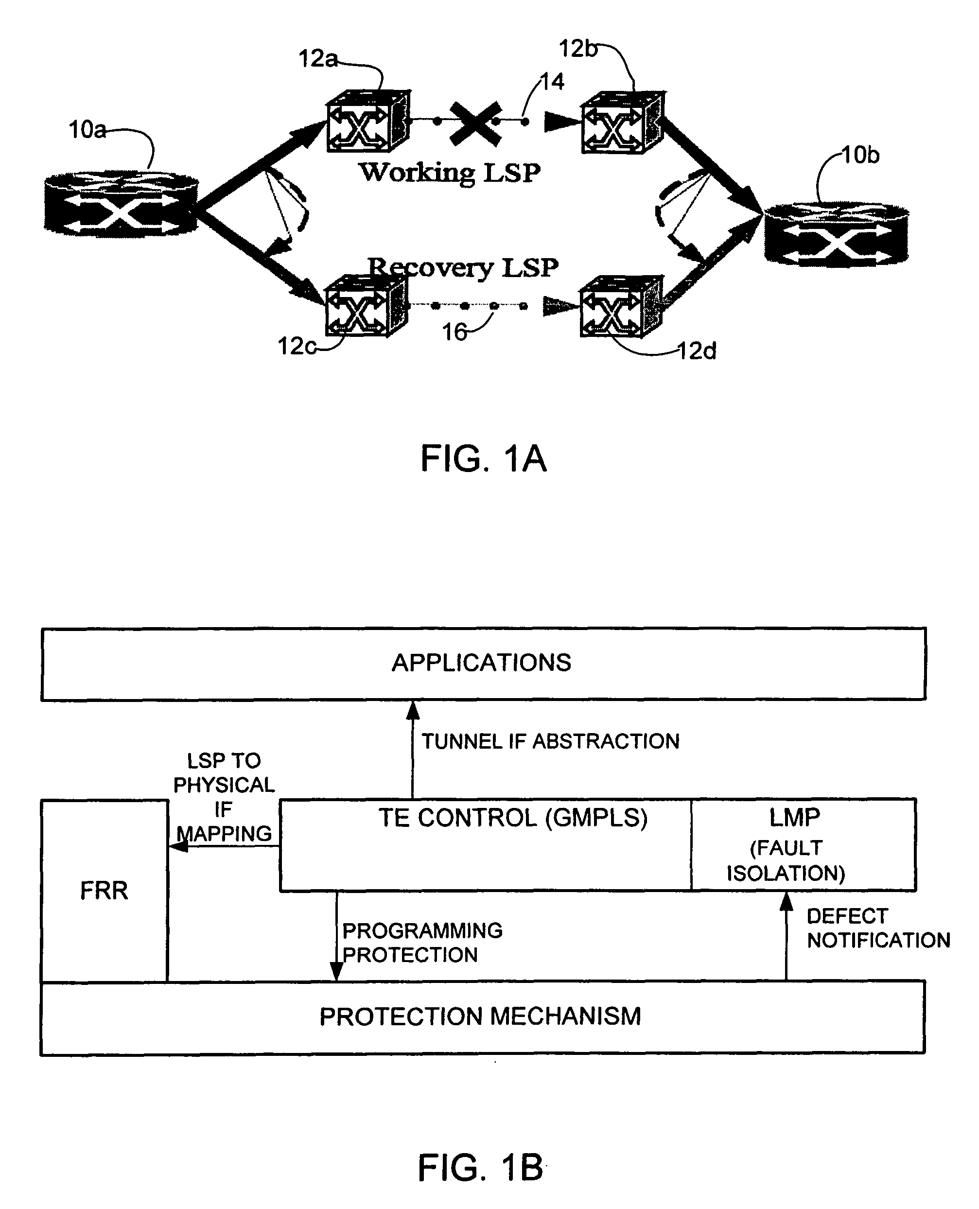
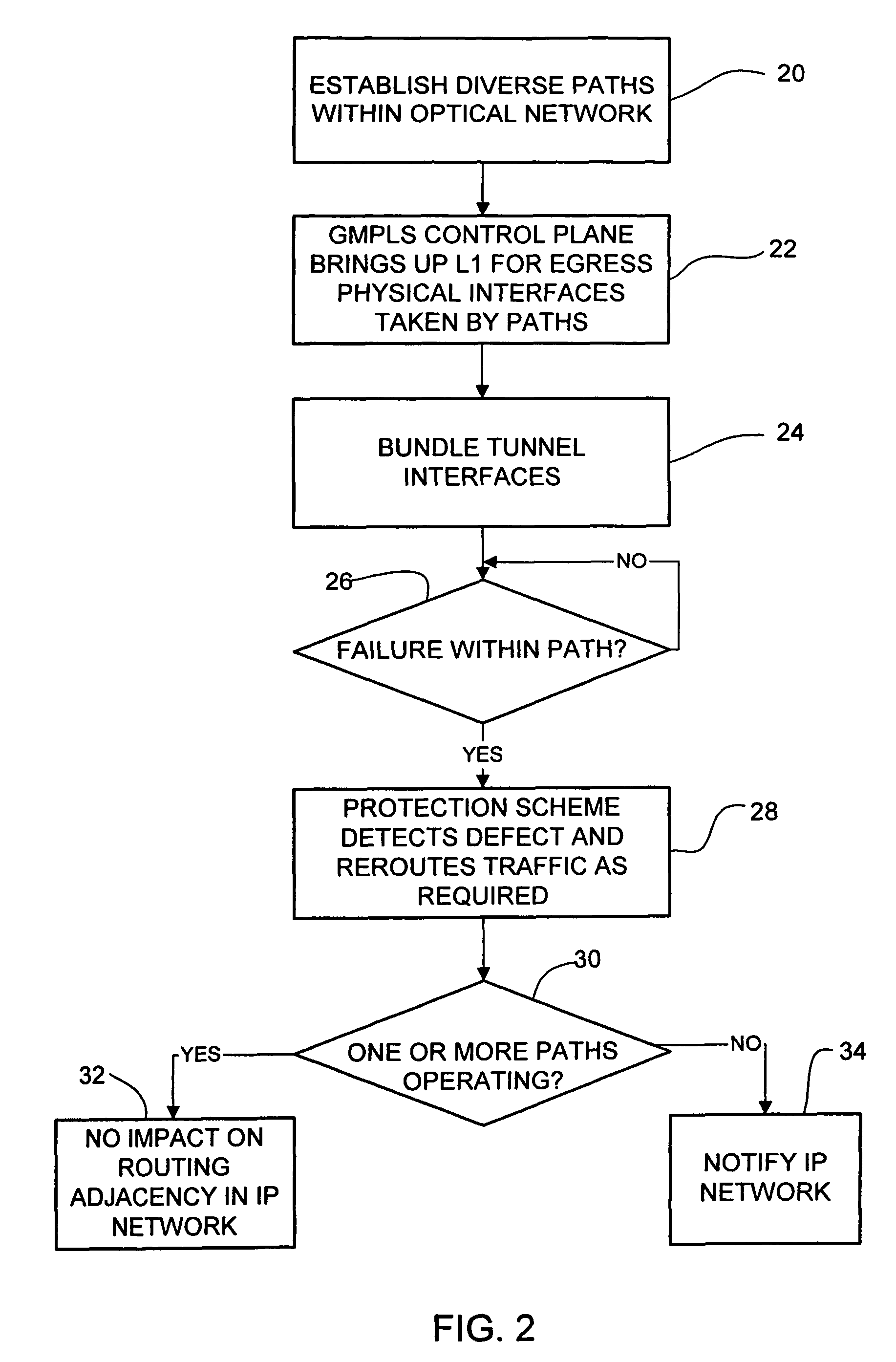
The patent describes a method and system for protecting paths in an optical network and integrating with link protection schemes in an IP network. The method involves establishing multiple paths in the optical network and grouping them in a dynamic bundle. This bundle is recognized as a single routing adjacency in the IP network, so changes within the bundle do not affect the routing in the IP network. The system includes a processor to create and manage the paths, and a protection module to synchronize with the data plane protection scheme. The technical effects of this invention include improved resilience and flexibility in protecting optical network paths, as well as seamless integration with IP network link protection schemes.

Problems solved by technology

Also, IP convergence is slower than any technique that optical networks can provide and there is a need for service isolation.
Conventional approaches for protection against failures in optical networks in the IP topology / traffic have the drawback that a failure in doing local restoration results in failure of routing adjacencies.

Method used


Image

  • Dynamic path protection in an optical network
  • Dynamic path protection in an optical network
  • Dynamic path protection in an optical network

Examples


Embodiment Construction

[0019]The following description is presented to enable one of ordinary skill in the art to make and use the invention. Descriptions of specific embodiments and applications are provided only as examples and various modifications will be readily apparent to those skilled in the art. The general principles described herein may be applied to other embodiments and applications without departing from the scope of the invention. Thus, the present invention is not to be limited to the embodiments shown, but is to be accorded the widest scope consistent with the principles and features described herein. For purpose of clarity, details relating to technical material that is known in the technical fields related to the invention have not been described in detail.

[0020]The present invention operates in the context of a data communication network including multiple network elements. A network element may be, for example, a terminal multiplexer, an add-drop multiplexer (ADM), photonic switch (PX...


PUM


Abstract

A method and system for dynamic protection of virtual links for paths of an optical network in communication with an IP network are disclosed. The method includes establishing two or more paths within the optical network and grouping the paths in a dynamic bundle. The grouping is selected at a control plane level and the bundle of paths are recognized as a single routing adjacency in the IP network so that as long as one or more paths within the bundle is operating, the routing adjacency in the IP network is not affected by changes within the bundle.

Description

BACKGROUND OF THE INVENTION[0001]The present invention relates generally to communication networks, and more specifically, to dynamic path protection in an optical network and integration with link protection schemes in an IP network.[0002]The rapid growth of the Internet and the widespread deployment of networks built around the Internet Protocol suite are creating a demand for new capabilities in IP (Internet Protocol) networks. MultiProtocol Label Switching (MPLS) provides a number of powerful capabilities such as traffic engineering, etc. As with IP routers, MPLS nodes use a routing protocol such as OSPF or IS-IS to calculate network paths and establish reachability. MPLS is an IETF (Internet Engineering Task Force) initiative that integrates Layer 2 information about network links (bandwidth, latency, utilization) into Layer 3 (IP) within a particular autonomous system in order to simplify and improve IP packet exchange. MPLS-TE provides network operators a great deal of flexib...

Claims


Application Information

Patent Timeline
Patent Type & Authority Patents(United States)
IPC IPC(8): H04J1/16H04L12/28
CPCH04L45/02H04L45/22H04L45/28H04L45/50H04J3/14H04L45/247
Inventor ZAMFIR, ANCAALI, ZAFARWARD, DAVID D.
Owner CISCO TECH INC
Learn More