Route protection in a communication network

a communication network and routing technology, applied in the field of routing protection in the communication network, can solve the problems of failure to get ip layer messages between peers, effective recovery path, and change may not avoid the faul

Inactive Publication Date: 2008-05-27
RPX CLEARINGHOUSE
View PDF12 Cites 22 Cited by
  • Summary
  • Abstract
  • Description
  • Claims
  • Application Information

AI Technical Summary

Benefits of technology

[0008]A further object of the invention is to provide an improved arrangement and method for the determination of protection paths in a communications network.

Problems solved by technology

Loss of IP adjacency supported by a failed fibre, however, only indicates that, at some SONET layer, or possibly due to a break in fibre, a failure to get IP layer messages between peers has occurred.
A particular problem with current fault recovery systems is that of determining an effective recovery path.
As the network upper and lower layers may have a differing topology, there is a risk that a minor ‘route around’ path change may not avoid the fault.
There is the further problem of determining the precise nature of the fault.
For example, it may not be easy to determine with any degree of rapidity whether a network failure has resulted from a fault in a switch, a router or a fibre path.

Method used


Image

  • Route protection in a communication network
  • Route protection in a communication network
  • Route protection in a communication network

Examples


Embodiment Construction

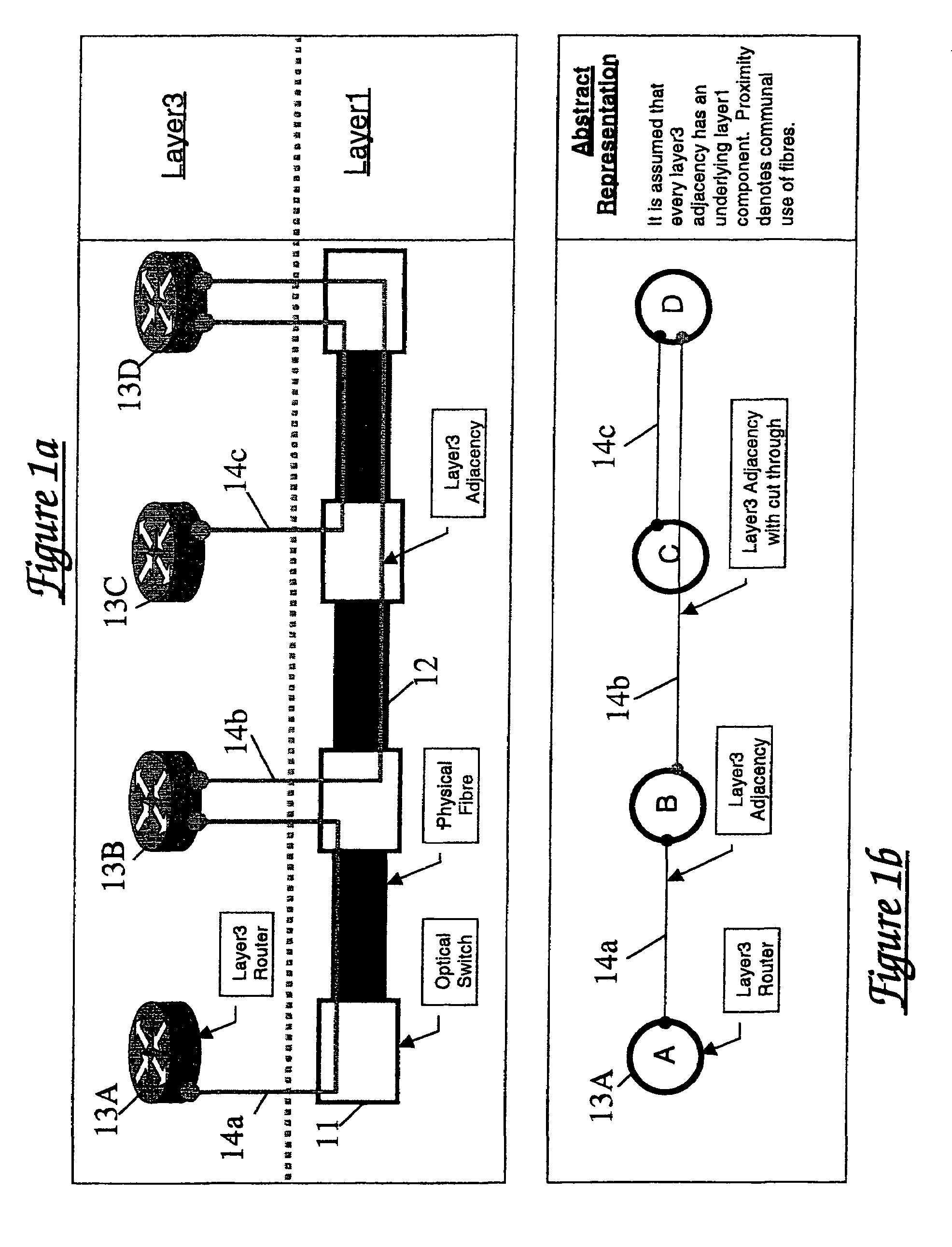
[0039]Referring first to FIG. 1a, this shows a multilayer network construction in highly schematic form. The network comprises a lower layer (layer 1 or physical layer) incorporating a plurality of switches 11 interconnected by optical fibre links 12. The upper layer or overlay (layer 3 or IP layer) of the network comprises a plurality of routers 13A to 13D. Although FIG. 1 shows each router being associated with a respective switch, this is not essential. As depicted schematically in FIG. 1b, layer 3 adjacencies 14a, 14b, 14c are defined between selected pairs of routers. It will of course be understood that although FIGS. 1a and 1b show four routers and four switches, a practical network will comprise a large number of such components.

[0040]It will of course be appreciated that, although the exemplary network of FIG. 1 has optical links between nodes, the path recovery techniques to be described below are equally applicable to networks having wired or wireless links, or free space...


PUM


Abstract

A communications network comprises a lower transport layer and an upper overlay incorporating a plurality of routers. Adjacencies are defined between respective pairs of routers. Path protection is provided by defining a software model of the overlay of the network and defining in the model a hierarchy of protection levels for the main path. Each protection level is characterised by a respective set of one or more broken adjacencies in the model, the adjacencies to be broken being determined from a knowledge of the underlying topology. A protection level is selected and a protection path avoiding the broken adjacencies associated with that protection level is calculated. If this calculated path is not available in the real network, a lower protection level in the hierarchy is selected and the protection path calculation repeated. The process continues until a suitable protection path is identified.

Description

FIELD OF THE INVENTION[0001]This invention relates to methods and arrangements for providing recovery from faults in a communications network and for calculating protection paths in such a network. The invention further relates to a network manager arranged to perform such path calculation.BACKGROUND OF THE INVENTION[0002]Modern communication networks are designed as a layered structure in which lower layers provide communication services for upper layers. These upper layers each have a topology which, when configured logically, may he referred to as an overlay topology. For efficiency reasons an overlay topology might not have a one-to-one correspondence with the underlying topology that supports it.[0003]Each layer commonly has its own responses to changes in the network, including alarms in the case of failure. A typical example of a layered topology which illustrates the interplay of alarms and layers is the case of a SONET or SDH (Synchronous Digital Hierarchy) ring supporting ...

Claims


Application Information

Patent Timeline
Patent Type & Authority Patents(United States)
IPC IPC(8): G06F15/173H04L12/56H04L69/40
CPCH04L41/0668H04L41/12H04L45/12H04L45/22H04L69/40
Inventor WEIL, JONMORRALL, ALEXODHAMS, DAVIDHAYWARD, KENNETHANDERSSON, LOA
Owner RPX CLEARINGHOUSE
Why Eureka
Try Eureka