Apparatus and method for optical communication protection

a technology of optical communication and apparatus, applied in the field of optical communication, can solve the problems of reduced protection level, non-correctability failure, and significant cost the addition of additional oc links to the optical communication network, and achieve the effect of increasing the efficiency of protection bandwidth

Inactive Publication Date: 2005-06-09
CIENA
View PDF10 Cites 22 Cited by
  • Summary
  • Abstract
  • Description
  • Claims
  • Application Information

AI Technical Summary

Benefits of technology

[0016] The present invention is directed to protection techniques within optical communication networks. Rather than using a line protection scheme as most current optical communication networks use, the present invention utilizes a path protection technique in which working and protection paths that are desired are assigned during network setup. During normal operations, only the working path is configured within the network elements' switch fabric, with protection paths being left unconfigured. The protection paths are assigned by having protection entries added to routing tables within the network elements of the working path. If a failure indication is detected

Problems solved by technology

The disadvantage of having separate links for the working and protection channels is the significant cost the additional OC links can add to the optical communication network.
The key disadvantage is the reduced level of protection that is established.
For instance, with such a protection architecture, the failure of two or more working channels that correspond to a single common protection channel is not protected against and will result in a non-correctable failure if no other protection scheme is in place.
Although these modifications allow for an adjustable configuration for the BLSR architecture, it is recognized that these modifications also add to the overall complexity of the optical communication network and therefore the difficulty to manage the network.
This complexity is especially prevalent when considering combinations of more than one of the above modifications within a single BLSR.
There are further difficulties with a BLSR architecture even when no modifications from the standard design are required, one of which is now described with reference to FIGS. 2A and 2B.
In both cases, t

Method used


Image

  • Apparatus and method for optical communication protection
  • Apparatus and method for optical communication protection
  • Apparatus and method for optical communication protection

Examples


Embodiment Construction

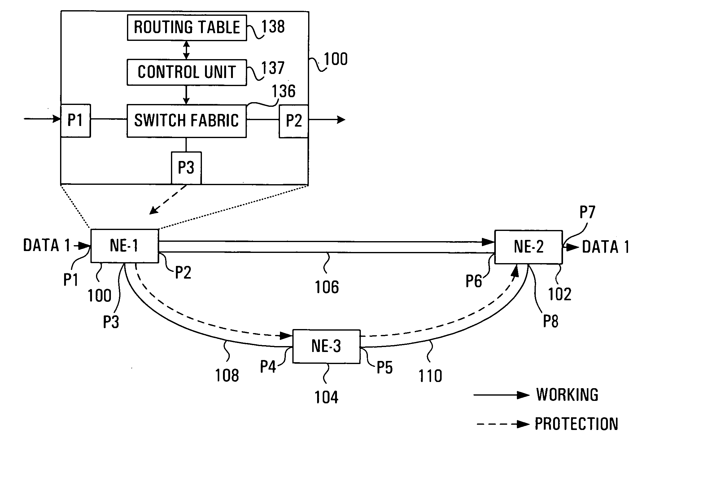
[0041] The present invention is directed to methods and apparatus used to improve protection switching within a communication network. Essentially, the present invention is a modified technique for protecting data traffic traversing Optical Carrier (OC) links. Unlike the well-known BLSR and linear line protection architectures, the modified technique described hereinbelow is directed at a path protection architecture in which working and protection paths are initially assigned but only the working path is normally configured within switch fabrics of the NEs. In the case of a failure in the working path, a protection path is configured in order to transfer, and therefore maintain, the data traffic flow.

[0042] In some embodiments, as will be described herein below, the protection path that is selected to be configured in times of failure is determined based upon the type and location of the failure. In other embodiments, only one protection path is configured for use in times of fail...


PUM


Abstract

Protection techniques within optical communication networks are extremely important. An alternative to a line protection scheme, as most current optical communication networks use, is to utilize a path protection technique in which working and protection paths that are desired are assigned during network setup. During normal operations, only the working path is configured within the network elements' switch fabric with protection paths being left unconfigured. If a failure indication is detected in the working path by a network element, a protection entry within a routing table of the network element is looked up to determine protection switching data that is required to switch the data traffic to the pre-assigned protection path. This protection switching data is inserted within the path overhead for the data traffic so that it can be communicated to all of the network elements that require their switch fabrics reconfigured to establish the protection path of communications. This protection technique allows for similar switching speed to that of line switching protection such as BLSR designs, but with an increase in efficiency in terms of protection bandwidth.

Description

RELATED APPLICATION [0001] This application is a continuation of U.S. patent application Ser. No. 09 / 620,248 filed in the name DeBoer, Evert E. et al.FIELD OF THE INVENTION [0002] This invention relates generally to optical communications and, in particular, to apparatus and methods used for protection of optical communications. BACKGROUND OF THE INVENTION [0003] Optical communication systems have become of critical importance within today's society. With this increase in importance comes a need for the optical communication infrastructures to maintain a high reliability and signal quality. To create these high standards, many techniques have been implemented. One extremely successful and wide spread method to maintain the integrity of communication networks, even during problem time periods, is through the use of line protection. [0004] The key principle behind line protection within optical communication networks is the generation of working and protection channels for each commun...

Claims


Application Information

Patent Timeline
IPC IPC(8): H04B10/032H04B10/07H04B10/077H04B10/275H04J3/00H04J3/08H04L12/56H04M3/00H04M3/22H04Q11/00H04Q11/04
CPCH04J3/085H04J2203/0053H04J2203/006H04L45/00H04L45/22H04Q2011/0092H04L45/54H04L45/62H04Q11/0005H04Q11/0062H04Q2011/0081H04L45/28
Inventor DEBOER, EVERT E.RYAN, DARRYL C.
Owner CIENA
Why Eureka
Try Eureka