Planar illumination device and liquid crystal display device using the planar illumination device as a backlight

a technology of liquid crystal display and planar illumination, which is applied in the direction of fixed installation, lighting and heating equipment, instruments, etc., can solve the problems of increasing the thickness of the backlight, reducing the luminous efficiency of the led chip, and affecting the appearance of irregular colors, etc., so as to reduce the thickness or thickness and size, reduce the weight saving, and reduce the power consumption

Active Publication Date: 2010-11-23
PANASONIC LIQUID CRYSTAL DISPLAY CO LTD
View PDF15 Cites 11 Cited by
  • Summary
  • Abstract
  • Description
  • Claims
  • Application Information

AI Technical Summary

Benefits of technology

[0008]If three colors are mixed, it is generally necessary that three LED chips approximate one another or are spaced apart from a liquid crystal display panel. However, the approximation of the LED chips has limitation and increases their temperatures to lower the luminous efficiency of the LED chips. In addition, increasing the distance between the LED chips and the display panel increases the thickness of the backlight, thereby hindering the downsizing and weight saving of the liquid crystal display device. Further, when a white planar illumination device is configured by arranging a large number of three-color LEDs, characteristic variations among the LEDs cause the uneven distribution of mixed colors and luminance.
[0009]It is an object of the present invention to provide a planar illumination device that achieves even distributions of mixed colors and luminance, downsizing and weight saving without lowering the luminous efficiency of an LED chip and a liquid crystal display device using the planar illumination device as a backlight.
[0015]The above-described planar illumination device according to the present invention can achieves even distributions of mixed colors and luminance, downsizing and weight saving without lowering the luminous efficiency of an LED chip. Needless to say, the planar illumination device can be applied to various technical fields while serving as a planar light source. In particular, the planar illumination device is here used as a backlight and combined with a liquid crystal display panel to thereby provide a liquid crystal display device that can be reduced in thickness or in thickness and size, provide lower power consumption and exhibit high-brightness and high-quality.

Problems solved by technology

In this case, since the LED chips are point light sources, irregular color tends to occur.
However, the approximation of the LED chips has limitation and increases their temperatures to lower the luminous efficiency of the LED chips.
In addition, increasing the distance between the LED chips and the display panel increases the thickness of the backlight, thereby hindering the downsizing and weight saving of the liquid crystal display device.
Further, when a white planar illumination device is configured by arranging a large number of three-color LEDs, characteristic variations among the LEDs cause the uneven distribution of mixed colors and luminance.

Method used


Image

  • Planar illumination device and liquid crystal display device using the planar illumination device as a backlight
  • Planar illumination device and liquid crystal display device using the planar illumination device as a backlight
  • Planar illumination device and liquid crystal display device using the planar illumination device as a backlight

Examples


first embodiment

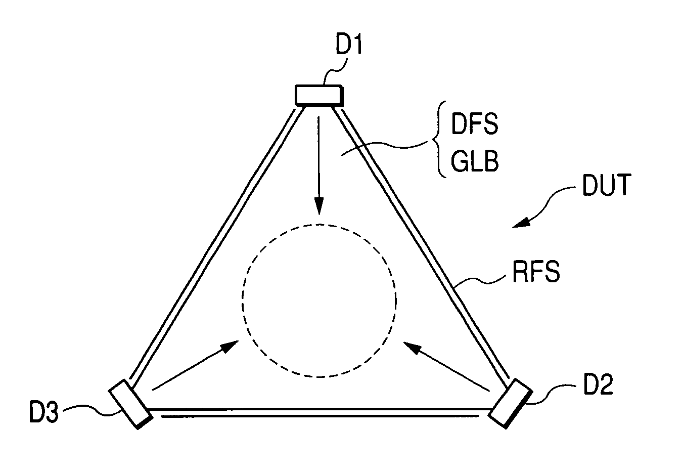
[0029]FIGS. 1A and 1B are schematics illustrating an essential part of a color mixing unit for assistance in explaining a planar illumination device according to a first embodiment of the present invention. FIG. 1A is a plan view and FIG. 1B is a side view as viewed from an arrow direction of FIG. 1A. FIG. 2 is a schematic of the undersurface of a light guide plate of FIGS. 1A and 1B. A backlight of the first embodiment is configured by arranging a plurality of color mixing units two-dimensionally.

[0030]A color mixing unit DUT shown in FIGS. 1A and 1B includes a transparent light guide plate GLB preferably made of an acryl resin plate, LED chips D1, D2, D3, a reflection sheet RFS, a reflection plate RFB, and a diffusion sheet DFS. The light guide plate GLB of the first embodiment is triangular and has three corners cut off to form cut faces CTF1, CTF2, CTF3 facing the center of the triangle. The LED chips D1, D2 and D3 are attached to the cut faces CTF1, CTF2 and CTF3, respectively....

second embodiment

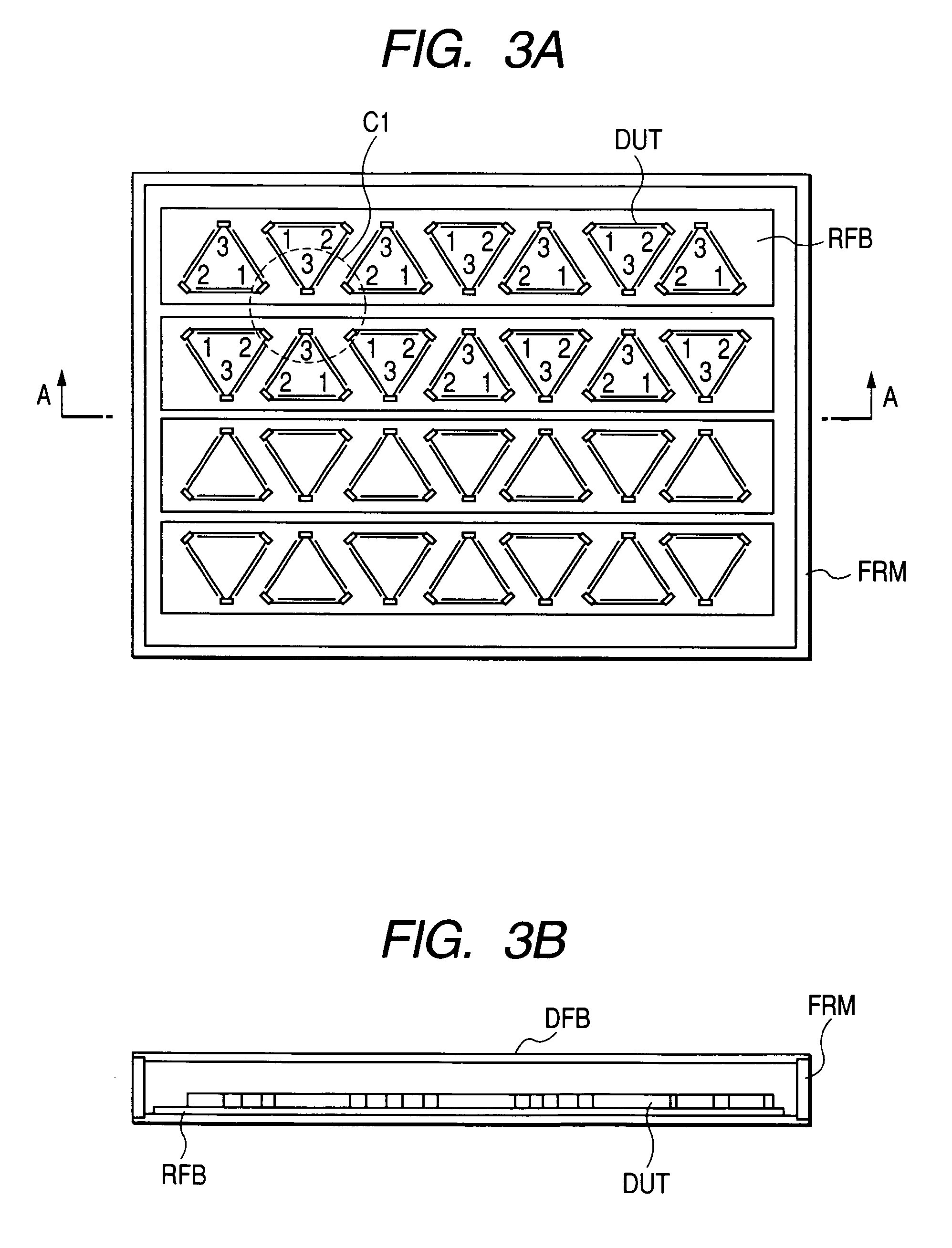
[0035]FIG. 4 is a plan view of a planar illumination device according to a second embodiment of the present invention similarly to FIG. 3A. A color mixing unit DUT has the same configuration as that of the first embodiment. In this embodiment, the color mixing units DUT are mounted on printed circuit boards RFB. The printed circuit boards FRB are arranged in a frame FRM in such a manner that their longitudinal directions are parallel to a lateral direction of FIG. 4. The color mixing units DUT placed in even rows of the printed circuit boards RFB are arranged with a shift of one color mixing unit in the lateral direction of FIG. 4. Also in this arrangement shown with a broken line ellipse C2, C3 in FIG. 4, LED chips emitting light with the same color are not adjacent to each other. Thus, even color mixture is ensured. The other configurations are the same as those of FIGS. 3A and 3B.

third embodiment

[0036]FIGS. 5A and 5B illustrate a planar illumination device according to a third embodiment of the present invention. FIG. 5A is a plan view and FIG. 5B is a side view taken along the white arrow of FIG. 5A. In the third embodiment, a light guide plate GLB is quadrangular and has four corners cut off to form cut faces CTF1, CTF2, CTF3 and CTF4 which face the center of the quadrangle. LED chips D1, D3, D2 and D3 are attached to the cut faces CTF1, CTF2, CTF3 and CTF 4, respectively. Similarly to FIG. 1, it is assumed that the LED chips D1, D2 and D3 emit red (R) light, green (G) light and blue (B) light, respectively.

[0037]In the third embodiment, the LED chips D1, D3, D2 and D3 are attached to the cut faces CTF1, CTF2, CTF3 and CTF4, respectively, of the quadrangular light guide plate GLB. A light mixing unit DUT of the third embodiment is the same as that described with FIG. 1 except that the light guide plate GLB is quadrangular and the four LED chips in total are each attached ...


PUM

PropertyMeasurementUnit
transparentaaaaaaaaaa
coloraaaaaaaaaa
color reproducibilityaaaaaaaaaa

Abstract

A planar illumination device is provided that can achieve even distributions of mixed colors and luminance, downsizing and weight saving without lowering the luminous efficiency of LED chips. In addition, a liquid crystal display device using the planar illumination device as a backlight is provided.A polygonal flat plate-like light guide plate GLB is combined with a plurality of LED chips D1, D2, D3 emitting light with different colors from each other to constitute a color mixing unit DUT. A plurality of the color mixing units are arranged on printed circuit boards RFB having a reflection function to constitute a planar illumination device. The planer illumination device is installed on the back of a liquid crystal display panel, thus constituting a liquid crystal display device.

Description

CLAIM OF PRIORITY[0001]The present application claims priority from Japanese Application JP 2005-368428 filed on Dec. 21, 2005, the content of which is hereby incorporated by reference into this application.BACKGROUND OF THE INVENTION[0002]The present invention relates generally to planar illumination devices and liquid crystal display devices using the planar illumination devices. In particular, the invention relates to an illumination device that uses a plurality of point light sources comprising solid light-emitting elements such as light-emitting diodes as illumination light sources for a liquid crystal display panel, mixes light from the point light sources and planarly emits the resulting white light or the desired resulting color light, and to a liquid crystal display device using the illumination device as a backlight.[0003]A liquid crystal display device is equipped with a illumination device in order to visualize electronic latent images formed on its liquid crystal displa...

Claims


Application Information

Patent Timeline
Patent Type & Authority Patents(United States)
IPC IPC(8): F21V7/04F21S2/00F21S8/04F21V8/00F21Y101/02G02F1/13357H01L33/00
CPCG02F1/133603G02F1/133605G02F2001/133613G02F1/133613
Inventor WATANABE, SABUROTOKUYAMA, HIROSHINISHIYAMA, SEIICHI
Owner PANASONIC LIQUID CRYSTAL DISPLAY CO LTD
Why Eureka
Try Eureka