Ion beam assisted deposition of thermal barrier coatings

a technology of thermal barrier coating and assisted deposition, which is applied in the direction of electric/magnetic/electromagnetic heating, machines/engines, mechanical equipment, etc., can solve the problems of difficult to achieve precise control of the thickness of the adhesion layer of the tgo, premature tbc failure, and the ability of the thermally grown alumina (tgo) layer to continue to grow thicker

Inactive Publication Date: 2010-11-23
NAT TECH & ENG SOLUTIONS OF SANDIA LLC
View PDF29 Cites 63 Cited by
  • Summary
  • Abstract
  • Description
  • Claims
  • Application Information

AI Technical Summary

Problems solved by technology

Excessively thick TGO layers (e.g., 10 microns) can cause premature TBC failures.
It is difficult to achieve precise control of the thickness of the TGO adhesion layer 16 due to many variables, including: the local oxygen concentration adjacent the part in the vacuum chamber, impurities (such as water vapor), non-uniform pre-heat temperature profiles across the part, the aluminum activity in the bond coat, surface impurities, exposure time, and specific temperature history (e.g., a longer heat-up time is needed for heavier parts).
Unfortunately, a thermally grown alumina (TGO) layer can continue to grow thicker during a conventional EBPVD process, due to the high substrate temperature (900-1100° C.).
This can result in an excessively thick or non-uniform TGO adhesion layer 16.

Method used


Image

  • Ion beam assisted deposition of thermal barrier coatings
  • Ion beam assisted deposition of thermal barrier coatings
  • Ion beam assisted deposition of thermal barrier coatings

Examples


first embodiment

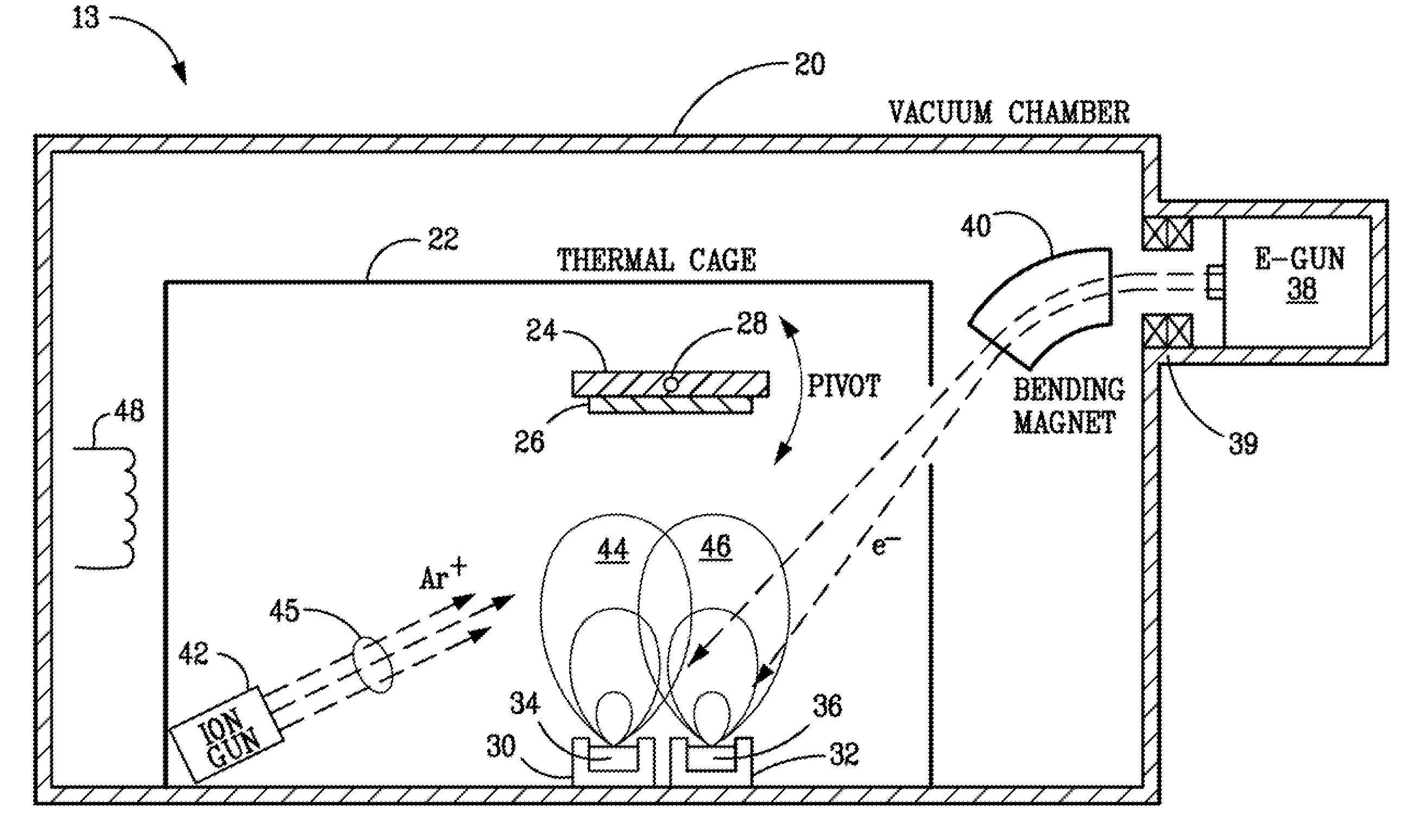
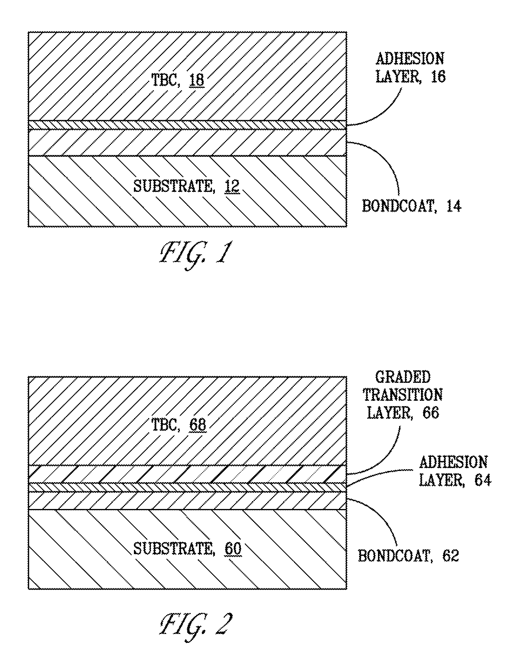
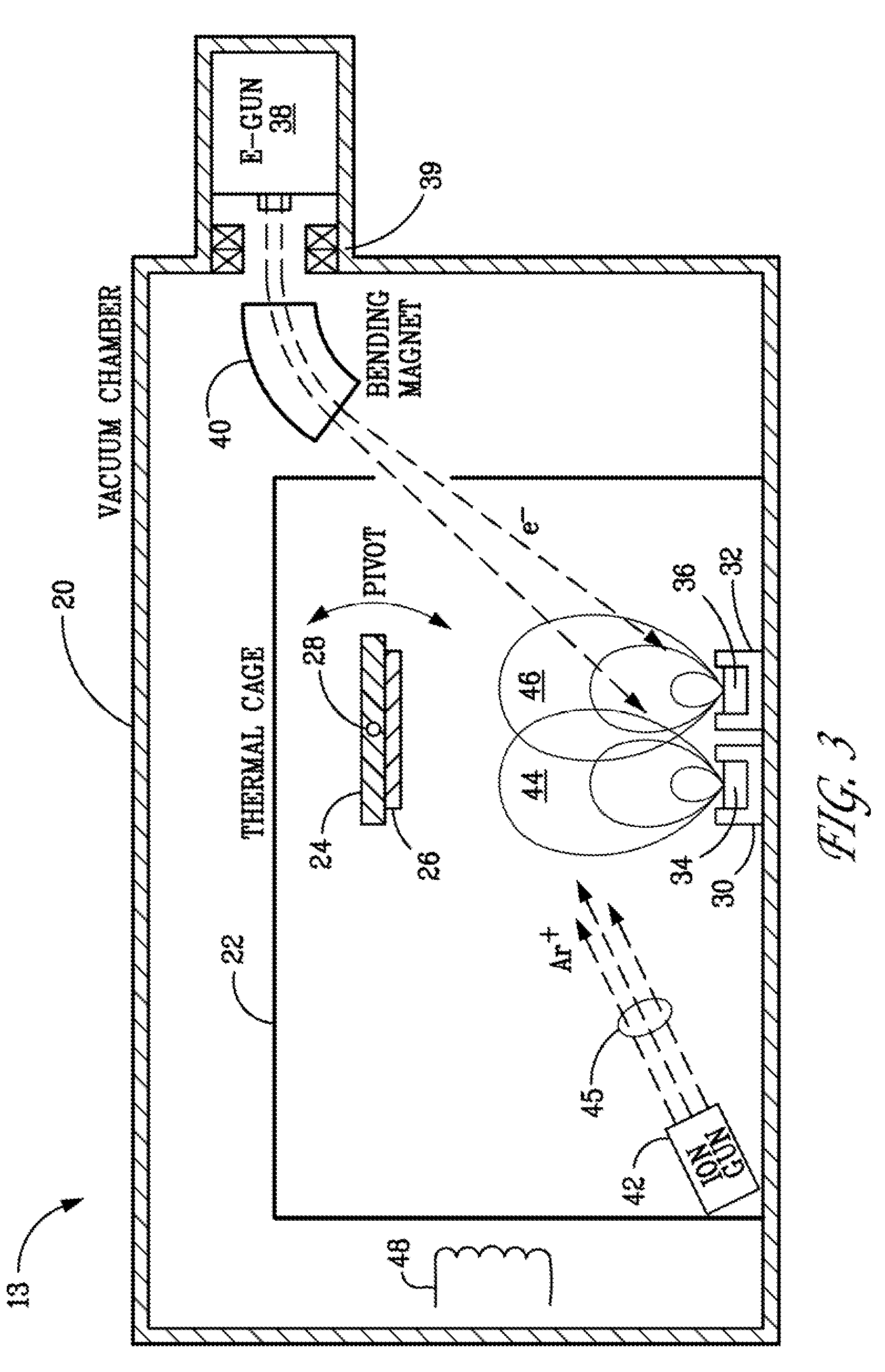
[0048]In a first embodiment, the invention comprises a process for coating a metallic substrate with alpha-phase alumina, comprising:[0049]a) preheating a metallic substrate to at least 500° C. in a vacuum chamber;[0050]b) exposing the pre-heated substrate to a plume of alumina evaporated from an alumina ingot heated with an electron beam;[0051]c) depositing alumina from the plume on to the substrate while simultaneously irradiating the deposit with a collimated beam of energetic ions; thereby transforming the deposited alumina into alpha-phase alumina; and[0052]d) stopping the process when a desired thickness of the alpha-phase alumina layer has been reached.

second embodiment

[0053]In a second embodiment, the invention comprises a process for coating a metallic substrate with a thermal barrier coating, comprising:[0054]a) providing a metallic substrate;[0055]b) preheating the substrate to at least 500° C. in a vacuum chamber;[0056]c) exposing the preheated substrate to a plume of YSZ evaporated from a YSZ ingot heated with an electron beam; and[0057]d) depositing YSZ from the plume onto the substrate while irradiating the deposit with a collimated beam of energetic ions; and[0058]e) stopping the process when a desired thickness of the thermal barrier coating has been reached.

third embodiment

[0059]In a third embodiment, the invention comprises a process for coating a metallic substrate with a thermal barrier coating, comprising:[0060]a) providing a metallic substrate pre-coated with a bondcoat layer;[0061]b) preheating the substrate to at least 500° C. in a vacuum chamber;[0062]c) depositing an adhesion layer onto the bondcoat; comprising:[0063]1) exposing the bondcoat to a plume of alumina evaporated from an alumina ingot heated with an electron beam; and[0064]2) depositing alumina from the plume onto the bondcoat while simultaneously irradiating the deposit with a collimated beam of energetic ions; thereby transforming the deposited alumina into alpha-phase alumina; then[0065]d) depositing a thermal barrier coating onto the adhesion layer; comprising:[0066]1) exposing the adhesion layer to a plume of YSZ evaporated from a YSZ ingot heated with the electron beam; and[0067]2) depositing YSZ from the plume onto the adhesion layer while irradiating the adhesion layer with...


PUM

PropertyMeasurementUnit
thicknessaaaaaaaaaa
thicknessaaaaaaaaaa
energyaaaaaaaaaa

Abstract

Methods and apparatus for depositing thermal barrier coatings on gas turbine blades and vanes using Electron Beam Physical Vapor Deposition (EBPVD) combined with Ion Beam Assisted Deposition (IBAD).

Description

CROSS-REFERENCE TO RELATED APPLICATIONS[0001]This application claims the benefit of U.S. provisional patent application Ser. No. 60 / 648,299 filed Jan. 28, 2005, which is incorporated herein by reference.FEDERALLY SPONSORED RESEARCH[0002]The United States Government has rights in this invention pursuant to Department of Energy Contract No. DE-AC04-94AL85000 with Sandia Corporation.BACKGROUND OF THE INVENTION[0003]The present invention relates generally to materials and methods used for depositing thermal barrier coatings on gas turbine blades / vanes using Electron Beam Physical Vapor Deposition (EBPVD) combined with Ion Beam Assisted Deposition (IBAD).[0004]Higher operating temperatures for gas turbine engines are continuously sought in order to increase their efficiency. Ceramic thermal barrier coatings (TBCs) have been used since the 1970's to protect gas turbine blades and vanes (typically made of iron, nickel, or cobalt-based superalloys) from oxidation and corrosion; and to minim...

Claims


Application Information

Patent Timeline
Patent Type & Authority Patents(United States)
IPC IPC(8): C23C14/08C23C14/48C23C14/30C23C14/54B05D3/06
CPCC23C14/024C23C14/027C23C14/081C23C14/083C23C14/30C23C14/48F05B2230/313
Inventor YOUCHISON, DENNIS L.MCDONALD, JIMMIE M.LUTZ, THOMAS J.GALLIS, MICHAIL A.
Owner NAT TECH & ENG SOLUTIONS OF SANDIA LLC
Why Eureka
Try Eureka