Method for making an environment-resistant and thermal barrier coating system on a component

a technology of thermal barrier coating and component, applied in the direction of superimposed coating process, vacuum evaporation coating, plasma technique, etc., can solve the problems of unsuitable in other circumstances, unacceptably high degradation rate, and component stress loading and high hea

Inactive Publication Date: 2008-06-05
HONEYWELL INT INC
View PDF19 Cites 15 Cited by
  • Summary
  • Abstract
  • Description
  • Claims
  • Application Information

AI Technical Summary

Problems solved by technology

Thus, the components of the engine are subjected to both high stress loadings and high heat (often in excess of 1090° C.).
The high stress and heat can cause erosion, oxidation, corrosion, and thermal fatigue cracks in the components, resulting in unacceptably high rates of degradation.
Although employing the above-mentioned processes produces environment-resistant coatings or top coat/bond coat systems that are useful in some circumstances, they may not be suitable in other circumstances.
In particular, p...

Method used


Image

  • Method for making an environment-resistant and thermal barrier coating system on a component
  • Method for making an environment-resistant and thermal barrier coating system on a component
  • Method for making an environment-resistant and thermal barrier coating system on a component

Examples


example 1

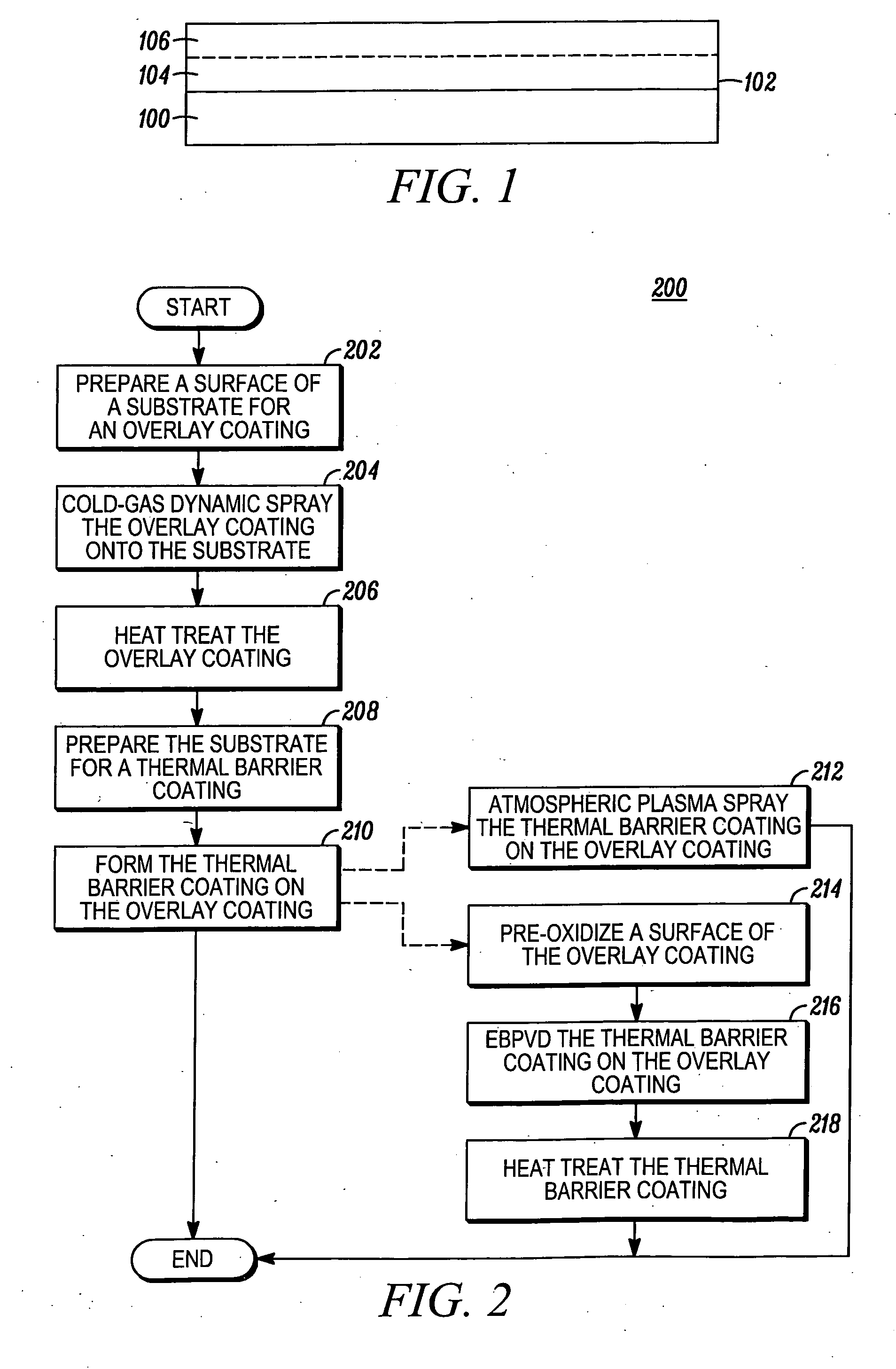
[0032]A powder made up of standard MCrAlY, specifically, Co32Ni21Cr8Al0.5Y, was cold sprayed onto a MARM 247 superalloy substrates to form a coating having a thickness of 0.25 mm. The same powder was also low pressure plasma sprayed (LPPS) onto other MARM 247 substrates to form a 0.25 mm coating thereon. LPPS is the technique currently used in production to apply this type of coating. Both substrates were then heat treated at 1093° C. for 4 hrs to diffuse and homogenize the coatings.

[0033]Both the substrates were tested in a static oxidation furnace at 1093° C. The atmosphere in the furnace was static air and the substrates were periodically weighed to determine weight change. As shown in FIG. 4, the overlay coating sprayed by LPPS lost significant weight (4 mg / cm2) after about 70 hrs, while the cold sprayed overlay coating did not experience the same weight loss until after about 700 hrs of exposure.

example 2

[0034]The cold sprayed and LPPS sprayed overlay coatings of example 1, were shot peened and vibro polished to a surface finish of between 1-5 microns and then coated with a 7% YSZ thermal barrier coating. The thermal barrier coatings were each about 0.20 mm in thickness and were formed in an EB-PVD vessel. These samples were then tested in a cyclic oxidation furnace at 1120° C. using a 1-hour cycle. The samples were held at temperature for 50 min. and then quickly pulled out of the furnace and held in ambient air for 10 min. before being quickly returned to the hot furnace. The thermal barrier coatings spalled off during cyclic oxidation test. The thermal barrier coating on the LPPS sprayed bond coat spalled off at just under half the time the thermal barrier coating spalled off on the cold sprayed bond coat. Thus, cold or warm spraying the MCrAlY coating onto a substrate increases the life of a subsequently formed thermal barrier coating by a factor of two.

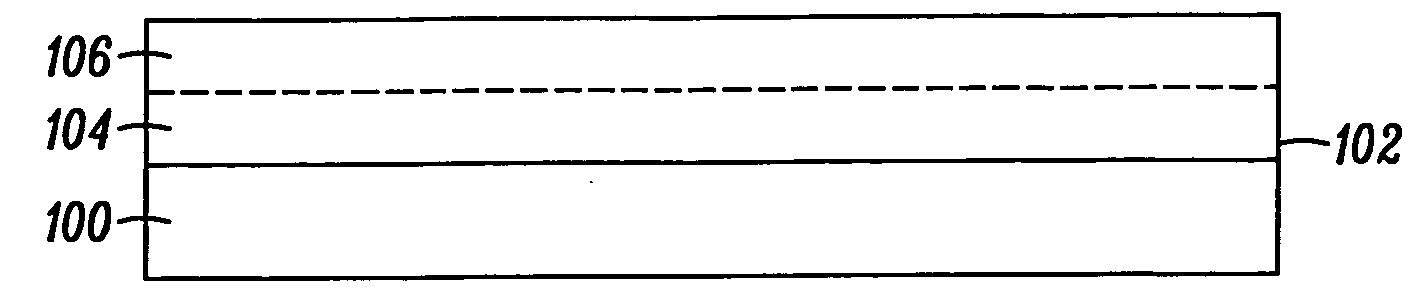
[0035]The coating system ...


PUM

PropertyMeasurementUnit
Temperatureaaaaaaaaaa

Abstract

Methods are provided for forming a coating system on a gas turbine component. In one embodiment, and by way of example only, the method includes cold spraying a material onto the component surface to form an overlay coating, the material comprising MCrAlY, wherein M comprises a constituent selected from the group consisting of Ni, Co, or Fe, or combinations of Ni, Co, and Fe. Then, the overlay coating is heat treated. The overlay coating is then shot peened and vibro polished. A thermal barrier coating is then applied onto the overlay coating to form the coating system via air plasma spaying or electron beam physical vapor deposition technique.

Description

TECHNICAL FIELD[0001]The present invention relates to coating metallic substrates, such as gas turbine engine components, with a coating having good bond strength, corrosion and oxidation as well as thermal resistance and, more particularly, to methods of forming environment-resistant and thermal barrier coating systems on the components.BACKGROUND[0002]Gas turbine engines, such as turbofan gas turbine engines, may be used to power various types of vehicles and systems, such as, for example, aircraft. During engine operation, generally, compressed air is mixed with fuel and burned, and the expanding hot combustion gases are directed against stationary turbine vanes in the engine. The vanes turn the high velocity gas flow partially sideways to impinge on turbine blades mounted on a rotationally mounted turbine disk or wheel.[0003]The force of the impinging gas causes the turbine disk to spin at high speeds and to produce power. When the high speed gas is passed out of the aft end of ...

Claims


Application Information

Patent Timeline
IPC IPC(8): B05D1/36B05D3/02B05D3/12C23C14/30C23C4/10
CPCB24C1/10C23C24/04Y02T50/67C23C28/3215C23C14/5806C23C28/3455C23C4/127C23C14/024C23C14/30C23C28/345C23C4/134Y02T50/60
Inventor HU, YIPINGRAYBOULD, DEREK
Owner HONEYWELL INT INC
Why Eureka
Try Eureka