Charging apparatus
a charging apparatus and charging circuit technology, applied in the direction of transportation and packaging, d ac network circuit arrangement, etc., can solve the problems of heavy load, heat produced, serious problems, etc., to reduce cost and area for implementation, reduce heat produced, and reduce the effect of heavy load
- Summary
- Abstract
- Description
- Claims
- Application Information
AI Technical Summary
Benefits of technology
Problems solved by technology
Method used
Image
Examples
embodiment 1
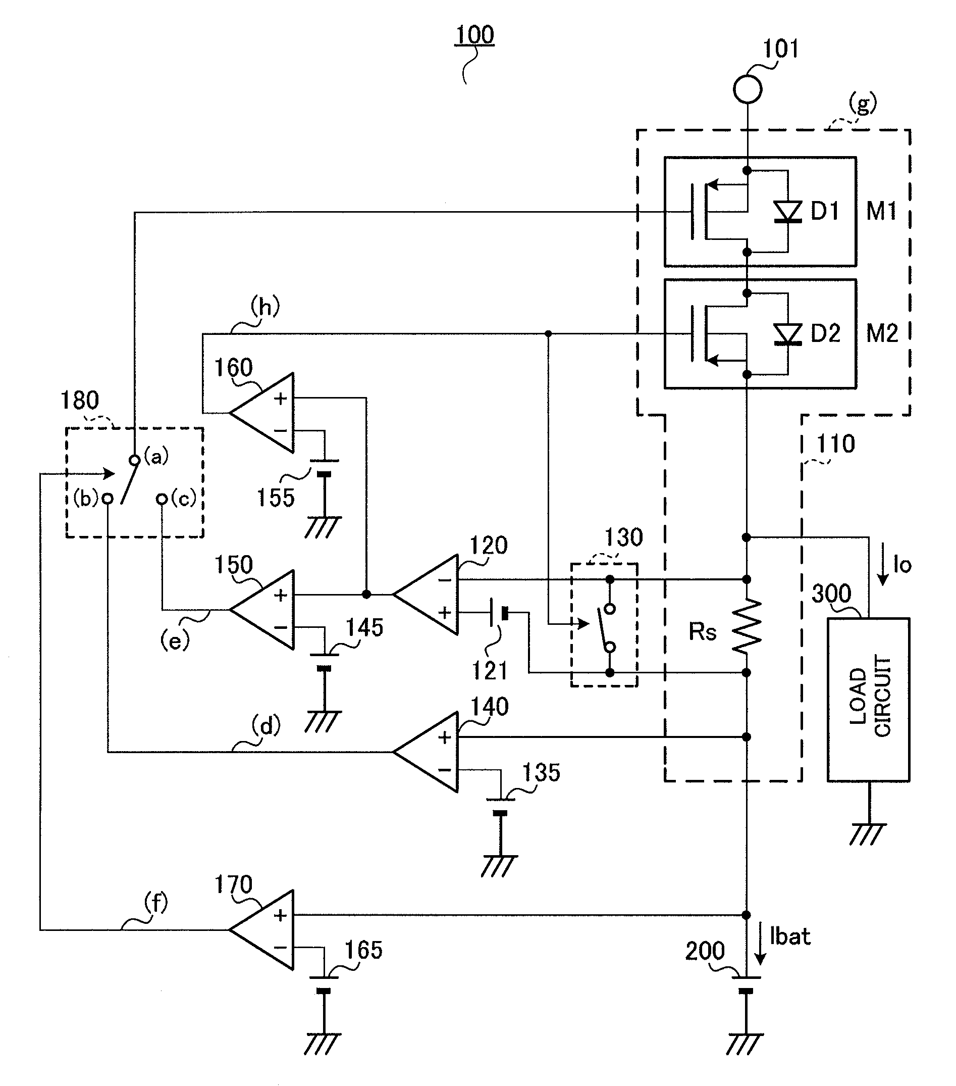
[0041]FIG. 3 is a circuit diagram showing a configuration of the charging apparatus according to Embodiment 1 of the present invention. An example will be described here with this embodiment where the charging apparatus is applied to charging control circuits that charge the batteries of mobile devices.
[0042]In FIG. 3, charging apparatus 100 charges battery 200 such as a lithium battery from an AC adapter which is a DC power supply, via a control transistor and current detecting resistance Rs.
[0043]Charging apparatus 100 adopts a configuration including: AC adapter input terminal 101 that receives an output DC voltage of an AC adapter; P-channel MOS transistors M1 and M2 (control transistors) that control charging current based on a signal of a terminal voltage (for example, gate terminal voltage); current detecting resistance Rs that detects the charging current of P-channel MOS transistors M1 and M2; charging section 110 that is configured with P-channel MOS transistors M1 and M2 ...
embodiment 2
[0069]FIG. 8 is a circuit diagram showing a configuration of the charging apparatus according to Embodiment 2 of the present invention. In this embodiment, the parts that are the same as those in FIG. 3 will be assigned the same reference numerals.
[0070]In FIG. 8, charging apparatus 400 has: AC adapter input terminal 101 that receives an output DC voltage of an AC adapter; charging section 110 that is configured with P-channel MOS transistors M1 and M2 and current detecting resistance Rs; current difference amplifier 120 that has a negative input terminal connected between P-channel MOS transistor M2 and current detecting resistance Rs, and a positive input terminal connected between current detecting resistance Rs and battery 200 via constant voltage source 121, and that amplifies the detected voltage of current detecting resistance Rs; switch 130 that short-circuits current detecting resistance Rs based on a comparison result of comparator 160; switch 410 that short-circuits the p...
PUM
 Abstract
Description
Claims
Application Information
 - R&D
- Intellectual Property
- Life Sciences
- Materials
- Tech Scout
- Unparalleled Data Quality
- Higher Quality Content
- 60% Fewer Hallucinations
Browse by: Latest US Patents, China's latest patents, Technical Efficacy Thesaurus, Application Domain, Technology Topic, Popular Technical Reports.
© 2025 PatSnap. All rights reserved.Legal|Privacy policy|Modern Slavery Act Transparency Statement|Sitemap|About US| Contact US: help@patsnap.com


