Heat dissipation device and computer using same

a heat dissipation device and laptop computer technology, applied in the direction of electrical apparatus casing/cabinet/drawer, semiconductor/solid-state device details, instruments, etc., can solve the problems of affecting device use, unstable electronic components, damage to components,

Inactive Publication Date: 2010-11-23
FURUI PRECISE COMPONENT (KUNSHAN) CO LTD +1
View PDF21 Cites 19 Cited by
  • Summary
  • Abstract
  • Description
  • Claims
  • Application Information

AI Technical Summary

Benefits of technology

[0005]With developments in technology, advanced components such as central processing units (CPUs) and video graphics array (VGA) chips feature increasingly high operating speeds, in addition to recent trends in design of laptop computers emphasizing light weight and compact profile, leaving little internal space for deployment of heat dissipation measures. Effective operation of the heat dissipation devices more often requires that an outer surface of the device be very close to an outer shell of the computer, such as near the keyboard, such that heat absorbed from the electronic components is transferred to the outer shell easily, detrimentally affecting device use.

Problems solved by technology

Electronic components in portable electronic apparatus, such as a laptop computer, can operate at very high speeds, which can, in turn, generate excessive heat, which can make the electronic components unstable, or even cause damage to the components thereof.
Effective operation of the heat dissipation devices more often requires that an outer surface of the device be very close to an outer shell of the computer, such as near the keyboard, such that heat absorbed from the electronic components is transferred to the outer shell easily, detrimentally affecting device use.

Method used


Image

  • Heat dissipation device and computer using same
  • Heat dissipation device and computer using same
  • Heat dissipation device and computer using same

Examples


first embodiment

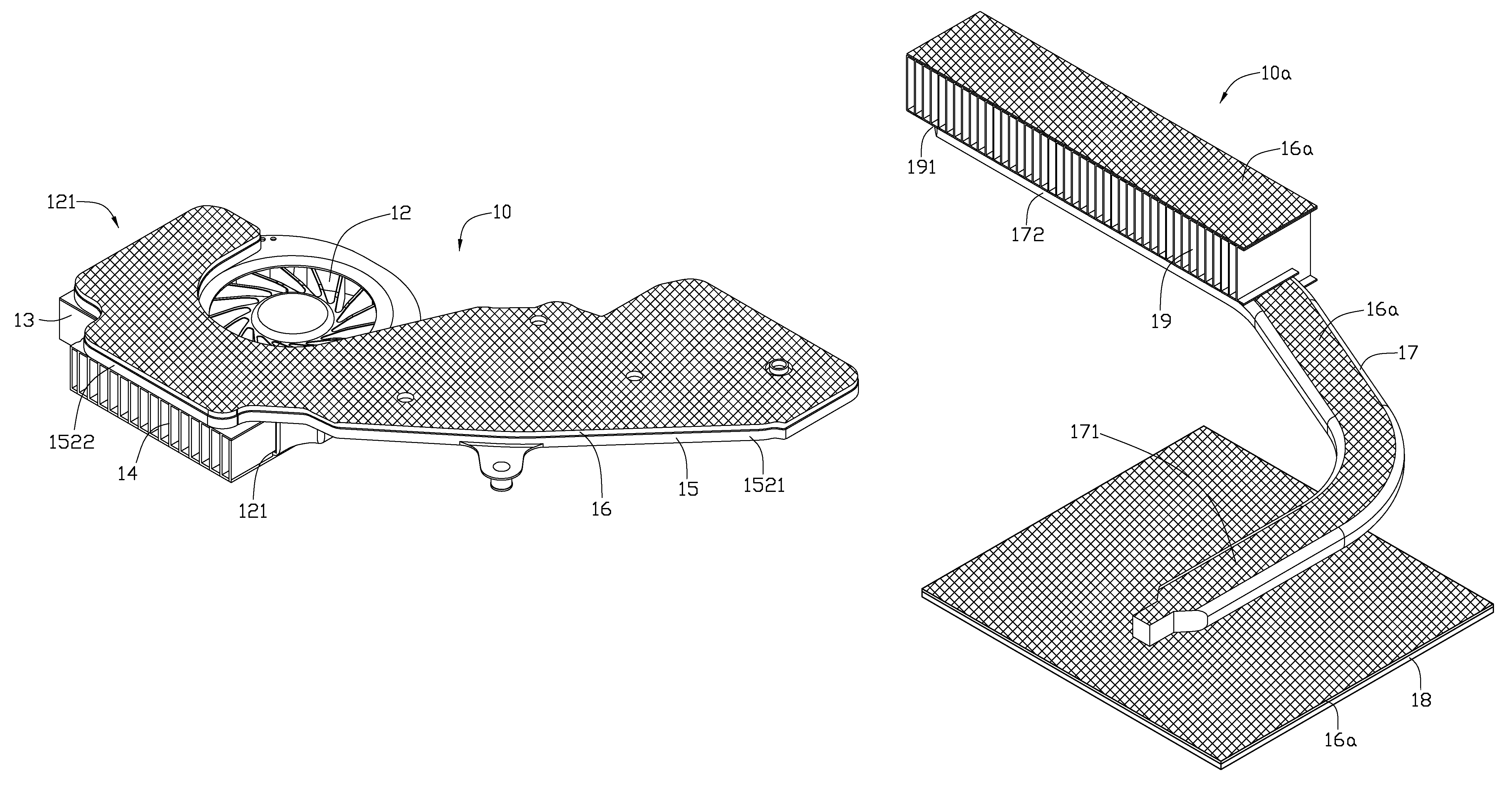
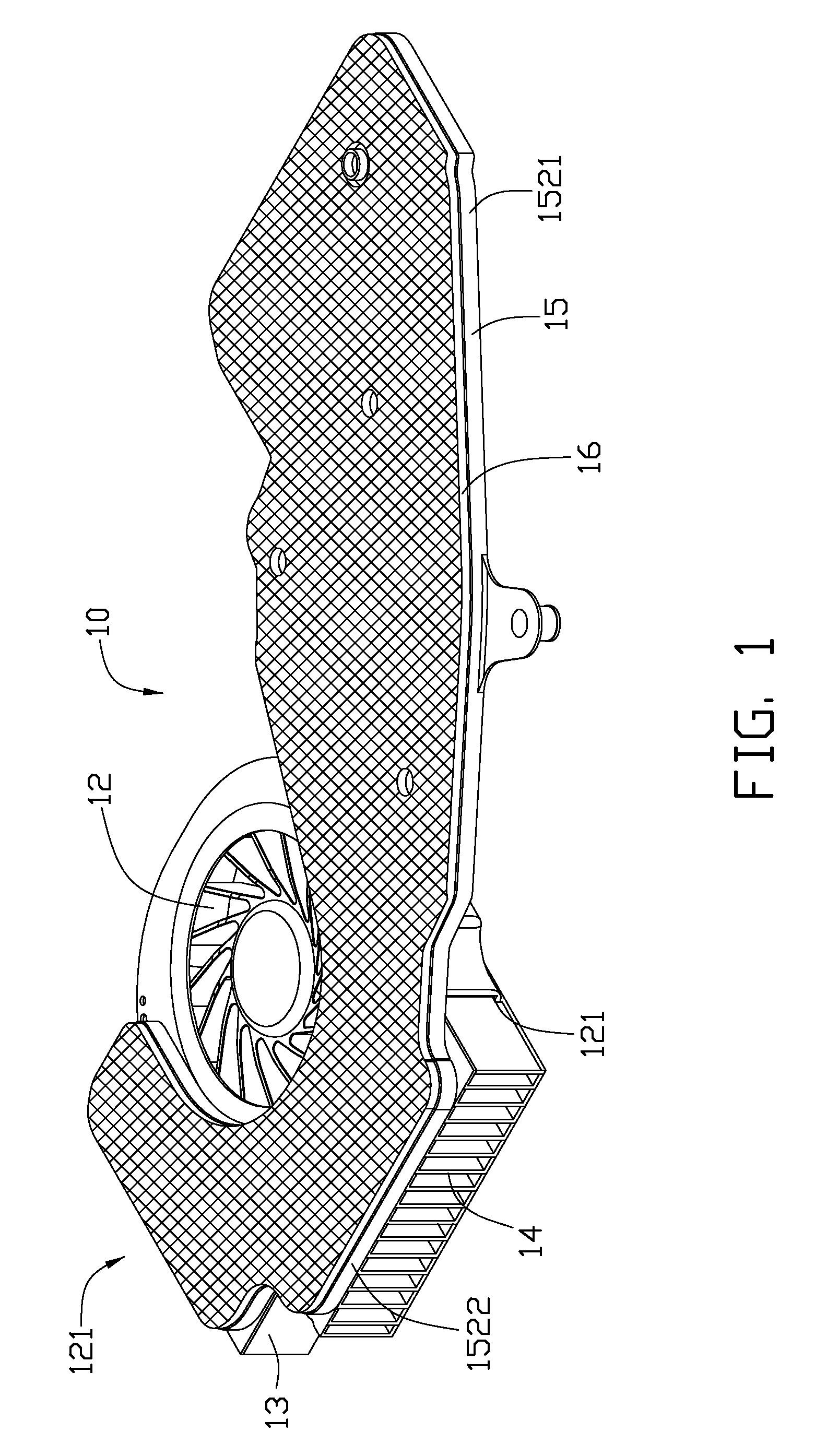
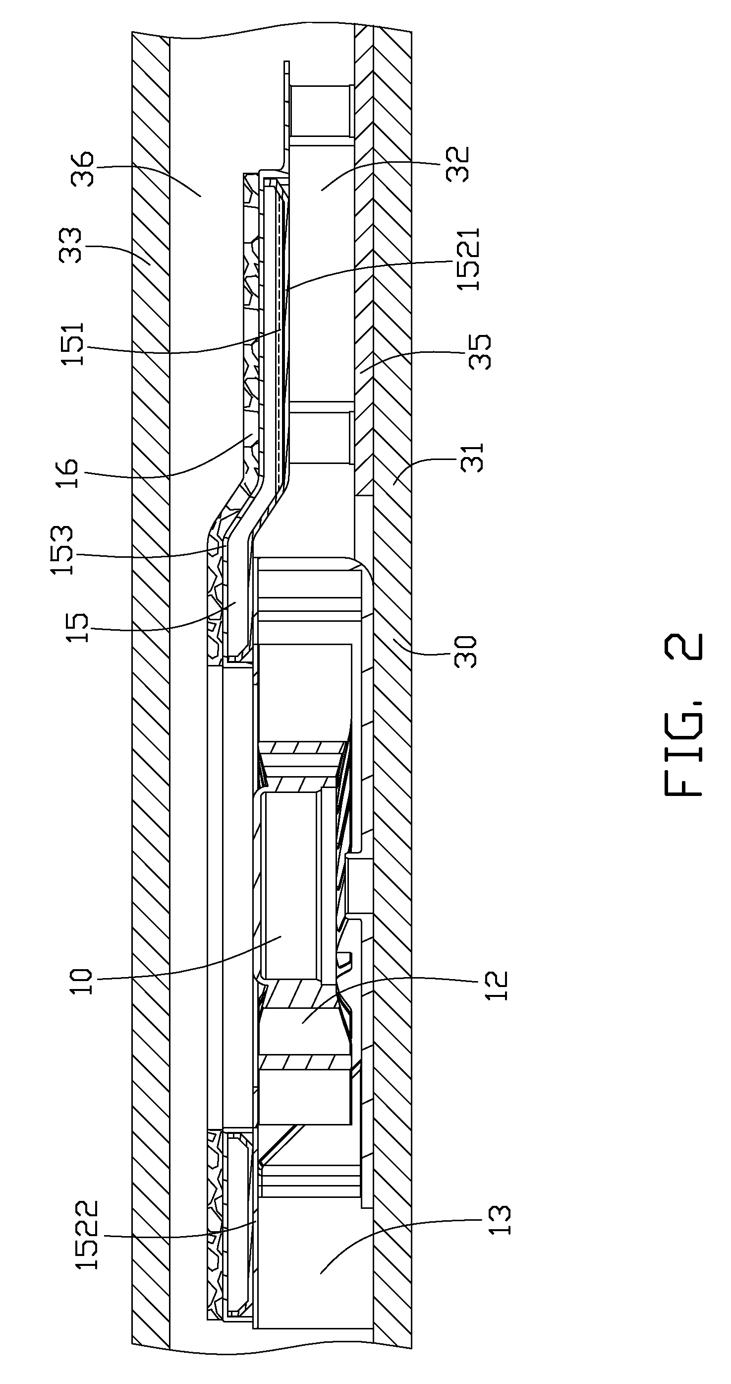
[0012]Referring to FIG. 1 and FIG. 2, a heat dissipation device 10 dissipating heat of an electronic component 32 of a laptop computer 30 in accordance with a first embodiment is shown.

[0013]The laptop computer 30 includes a bottom cover 31, a printed circuit board 35 and an opposite top cover 33 with a keyboard (not shown) situated thereon. The top and bottom covers 33, 31 are parts of a shell (not labeled) of the laptop computer 30. The bottom cover 31 and the top cover 33 cooperatively form an internal space 36 receiving the printed circuit board 35, the electronic component 32, and the heat dissipation device 10 therein. The internal space 36 is slightly taller than the heat dissipation device 10.

[0014]The heat dissipation device 10 includes a heat spreader 15, a centrifugal fan 12, a first fin unit 13, and a second fin unit 14. The centrifugal fan 12 defines first and second air outlets 121 in perpendicular side surfaces thereof, accommodating the first fin unit 13 and the seco...

second embodiment

[0020]FIG. 4 is a schematic cross-section of the heat spreader 15 of the heat dissipation device 10 coated with a heat isolation layer 16a according to a The heat isolation layer 16a includes a sheet of polyurethane rigid foam 161 and an adhesive layer 162 connecting the polyurethane rigid foam 161 with the top wall 153 of the heat spreader 15. The heat isolation layer 16a is formed by cutting a pre-formed polyurethane foam into a thin sheet corresponding in shape and size to top wall 153 of the heat spreader 15, which is then affixed to the top surface of the heat spreader 15 by the adhesive layer 162.

[0021]FIG. 5 illustrates a heat dissipation device 10a incorporating the heat isolation layer 16a of FIG. 4. The heat dissipation device 10a includes a heat absorbing block 18, a heat spreader 17, and a fin unit 19. In this embodiment, the heat spreader 17 is a heat pipe which forms an evaporating section 171 and a condensing section 172 at two ends thereof, and a cutout 191 defined ...


PUM


Abstract

A heat dissipation device includes a fin unit, a heat spreader and a heat isolation layer. The heat spreader contacts the fin unit and transfers heat to the fin unit for dissipation. The heat isolation layer is coated on an outer surface of the heat dissipation device. The heat isolation layer is polyurethane foam.

Description

BACKGROUND[0001]1. Technical Field[0002]The disclosure relates to heat dissipation, and particularly to a heat dissipation device for a laptop computer.[0003]2. Description of Related Art[0004]Electronic components in portable electronic apparatus, such as a laptop computer, can operate at very high speeds, which can, in turn, generate excessive heat, which can make the electronic components unstable, or even cause damage to the components thereof. Therefore, heat must be removed efficiently to ensure normal operation.[0005]With developments in technology, advanced components such as central processing units (CPUs) and video graphics array (VGA) chips feature increasingly high operating speeds, in addition to recent trends in design of laptop computers emphasizing light weight and compact profile, leaving little internal space for deployment of heat dissipation measures. Effective operation of the heat dissipation devices more often requires that an outer surface of the device be ve...

Claims


Application Information

Patent Timeline
Patent Type & Authority Patents(United States)
IPC IPC(8): G06F1/20H05K7/20
CPCG06F1/203H01L23/3735H01L23/3737H01L23/427H01L23/467H01L2924/0002H01L2924/00
Inventor HWANG, CHING-BAIMENG, JIN-GONGLIANG, CHENG-JEN
Owner FURUI PRECISE COMPONENT (KUNSHAN) CO LTD
Why Eureka
Try Eureka