Turbomachine comprising a system for cooling the downstream face of an impeller of a centrifugal compressor

a centrifugal compressor and impeller cooling technology, which is applied in the field of turbomachines, can solve the problems of increasing airflow, degrading its performance, increasing the weight and rotational inertia of the impeller, etc., and achieves the effect of reducing the performance of the turbomachine, simple, effective and economic solution

Active Publication Date: 2010-11-30
SN DETUDE & DE CONSTR DE MOTEURS DAVIATION S N E C M A
View PDF10 Cites 19 Cited by
  • Summary
  • Abstract
  • Description
  • Claims
  • Application Information

AI Technical Summary

Benefits of technology

[0008]The object of the invention is in particular to provide a simple, effective and economic solution to these problems associated with ventilating the downstream cavity of the impeller of a centrifugal compressor in a turbomachine, without causing a reduction in the performance in the turbomachine.
[0009]Accordingly, it proposes a turbomachine comprising a diffuser-distributor assembly arranged at the outlet of the impeller of a centrifugal compressor and supplying an annular combustion chamber with air and means for injecting air for ventilating a turbine, this diffuser-distributor assembly comprising an annular downstream end-piece connected at its downstream end to the injection means and delimiting, with the downstream face of the impeller, an annular cavity for the circulation of ventilation air taken from the outlet of the compressor, which comprises means for drawing off, from the injection means, a fraction of said turbine ventilation airflow, and means for guiding the drawn-off air to the radially internal portion of the downstream face of the impeller, so that this airflows radially from inside to outside along the downstream face of the impeller and mixes with the air taken from the outlet of the compressor in order to reduce the temperature of the air in the annular cavity.
[0010]The ventilation air drawn off at the injection means of the circuit for ventilating the turbine is guided to the downstream face of the impeller and sweeps this downstream face, and is then mixed in the downstream cavity of the impeller with the air taken from the outlet of the compressor, which reduces the temperature of the air in this cavity. This cooling of the impeller makes it possible to have a higher air compression ratio than that of the prior art. In addition, the air for cooling the downstream face of the impeller is taken from the means for injecting air into the turbine ventilation circuit, which makes it possible to not reduce the flows of working air and therefore to maintain the performance of the turbomachine.

Problems solved by technology

However, this increases the airflows not working in the turbomachine and degrades its performance.
However, attaching this shield to the impeller is complex and causes an increase in the weight and rotational inertia of the impeller, which reduces the performance of the turbomachine.

Method used


Image

  • Turbomachine comprising a system for cooling the downstream face of an impeller of a centrifugal compressor
  • Turbomachine comprising a system for cooling the downstream face of an impeller of a centrifugal compressor
  • Turbomachine comprising a system for cooling the downstream face of an impeller of a centrifugal compressor

Examples


Embodiment Construction

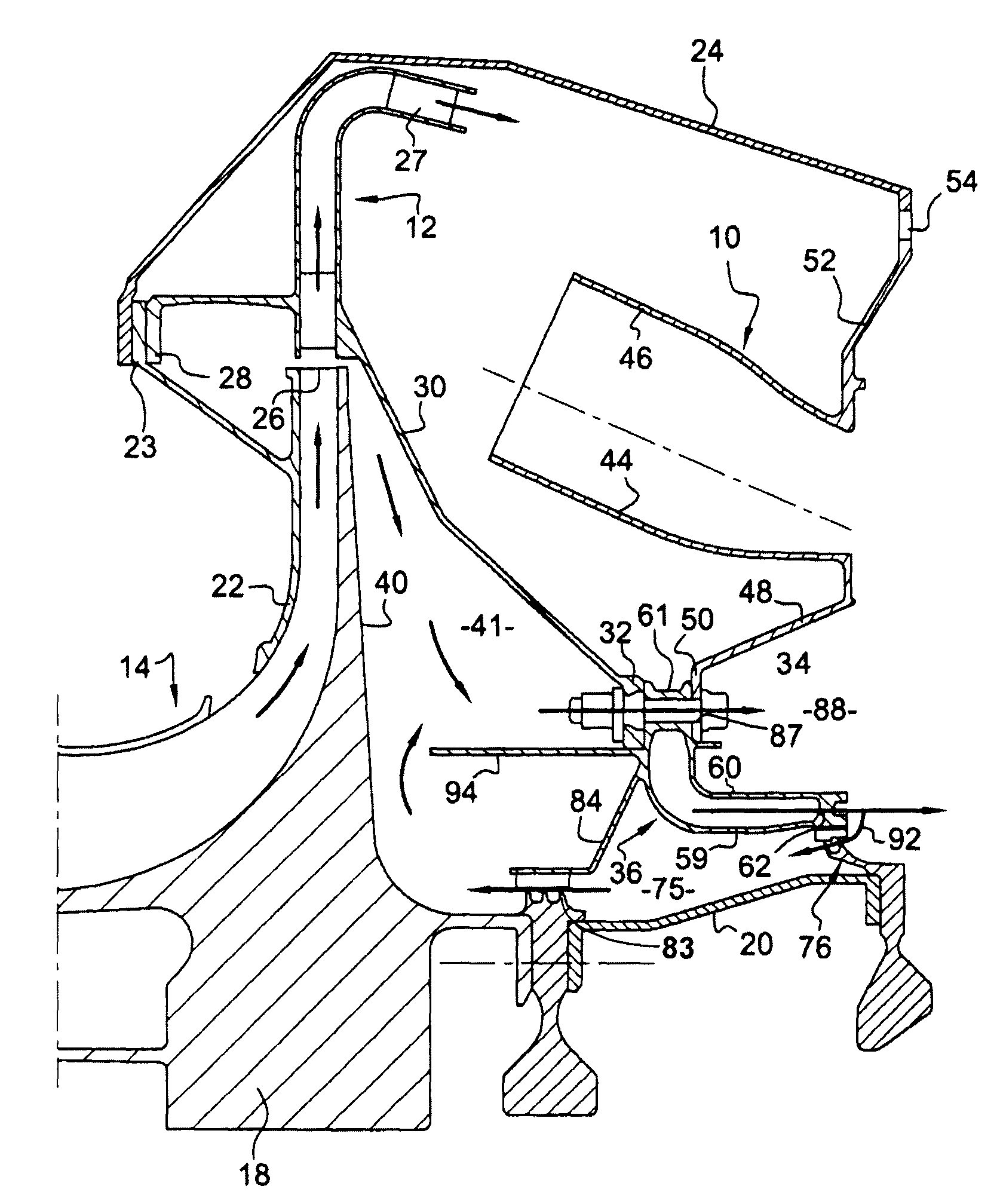
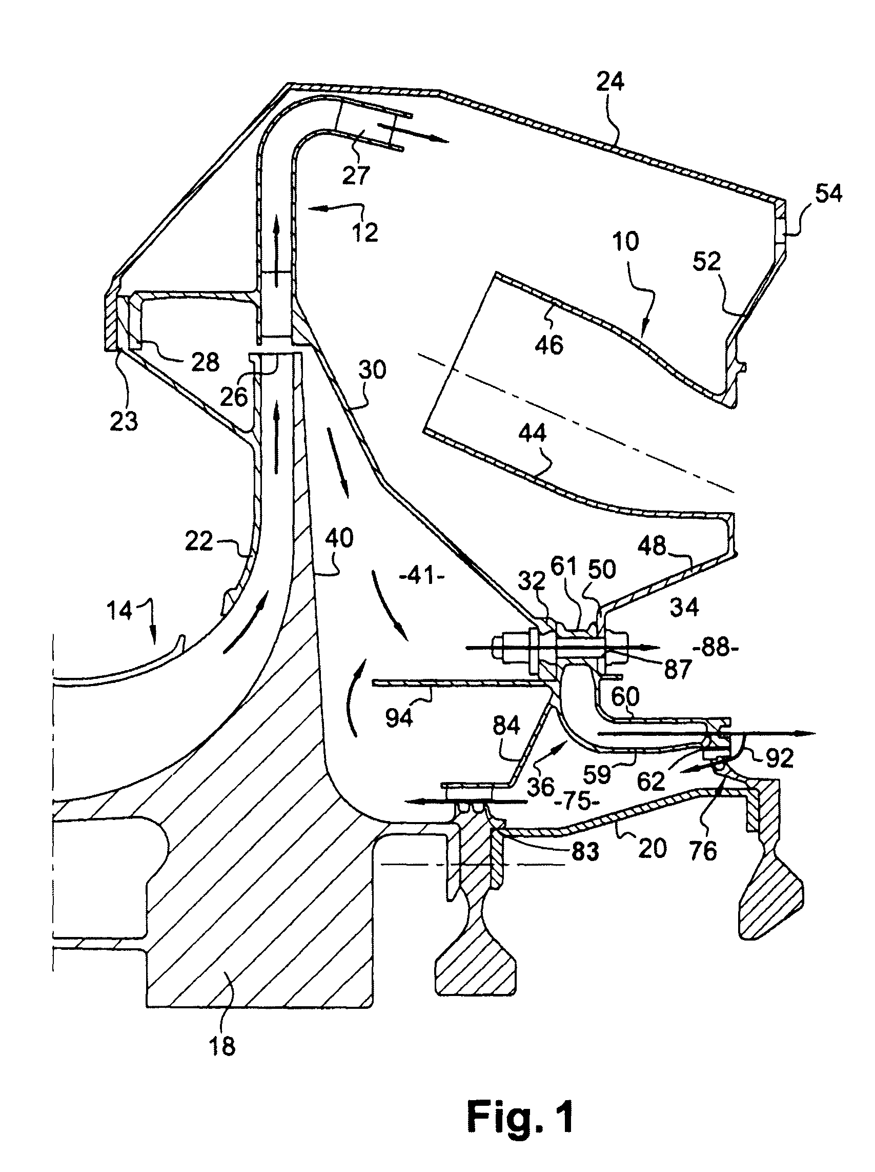
[0018]FIG. 1 represents a portion of a turbomachine, such as an aircraft turbojet or turboprop, comprising, from upstream to downstream, in the direction of the flow of gases inside the turbomachine, a compressor centrifugal stage 14, an annular diffuser-distributor assembly 12 and a combustion chamber 10.

[0019]The centrifugal compressor stage 14 comprises an impeller 18 connected to a portion of shaft 20, and a stator 22 connected via an upstream annular flange 23 to an external casing 24 of the turbomachine that extends around the compressor 14, the diffuser 12 and the combustion chamber 10.

[0020]The outlet 26 of the compressor is oriented radially outward and aligned with the inlet of the diffuser 12, the outlet of the compressor 14 being separated from the inlet of the diffuser 12 by a small radial clearance. The diffuser 12 has a bent annular shape and is connected to the distributor 27 which opens radially onto the outside of the inlet of the combustion chamber 10.

[0021]The di...


PUM


Abstract

A turbomachine comprising a diffuser—distributor assembly comprising a downstream end-piece connected at its downstream end to means for injecting air for ventilating a turbine and delimiting with the impeller of a centrifugal compressor an annular cavity for the circulation of ventilation air taken from the outlet of the compressor, this turbomachine comprising means for taking air from the injection means and means for guiding this air to the radially internal portion of the downstream face of the impeller.

Description

[0001]The present invention relates to a system for cooling the downstream face of an impeller of a centrifugal compressor in a turbomachine such as in particular an aircraft turbojet or turboprop.BACKGROUND OF THE INVENTION[0002]In a turbomachine of which the final stage of the compressor is of the centrifugal type, a diffuser-distributor assembly is arranged at the outlet of the centrifugal stage and supplies an annular combustion chamber with air.[0003]The diffuser comprises an annular downstream end-piece that is connected at its downstream end to means for injecting air into a circuit for ventilating a turbine situated downstream of the combustion chamber. A portion of the airflow coming out of the distributor flows round the combustion chamber via the inside, while passing between a radially internal wall of the chamber and the end-piece of the diffuser, to supply these air injection means for ventilating the turbine.[0004]An annular cavity is delimited downstream of the impel...

Claims


Application Information

Patent Timeline
Patent Type & Authority Patents(United States)
IPC IPC(8): F02C7/18
CPCF01D5/046F01D5/081Y02T50/671Y02T50/676F05D2260/205F04D29/284F04D29/584Y02T50/60
Inventor BEHAGHEL, LAURENTMOURLAN, JEAN-PIERRE ANDRE JOSEPHSTANGALINI, GERARD JACQUES
Owner SN DETUDE & DE CONSTR DE MOTEURS DAVIATION S N E C M A
Why Eureka
Try Eureka