Injection molding machine having a heat insulated barrel

a technology of injection molding machine and heat insulation barrel, which is applied in the field of heat insulation structure, can solve the problems of increasing the load of air conditioner, increasing and affecting the operation efficiency of the machine, so as to reduce the effect of the temperature of the operation environment on the temperature in the barrel and the temperature of the operation region

Inactive Publication Date: 2010-11-30
MINGSHUO COMP (SUZHOU) CO LTD +1
View PDF3 Cites 6 Cited by
  • Summary
  • Abstract
  • Description
  • Claims
  • Application Information

AI Technical Summary

Benefits of technology

[0011]To sum up, according to the injection molding machine of the invention, the heat-insulating units respectively including a plurality of layers cover the outer surface of the barrel one after another, thus to insulate the heat generated from the barrel by heat radiation in the operation of the injection molding machine, to reduce the temperature of the operation region, and to reduce power consumption of the air conditioner in the operation region. At the same time, the effect of the temperature of the operation environment on the temperature in the barrel can decrease, thereby improving quality of injection products.

Problems solved by technology

Therefore, heat generated from the barrel by heat radiation directly dissipates into the operation environment, thereby causing a high temperature of an operation region of the injection molding machine and worsening the operation environment of operators.
Further, if the injection molding machine is disposed in a room having an air conditioner, the load of the air conditioner greatly increases, thereby increasing power consumption.
However, since the barrel is exposed to the operation environment, the temperature of the operation environment has a great effect on the temperature of the molten plastic.
Further, as the flow speed decreases, the temperature of the molten plastic decreases, thereby causing a vicious circle.
Further, as the flow speed increases, the temperature of the molten plastic decreases less, and the flow speed increases, thereby also causing a vicious circle.
Thus, the quality of the injection products is greatly affected.

Method used


Image

  • Injection molding machine having a heat insulated barrel
  • Injection molding machine having a heat insulated barrel
  • Injection molding machine having a heat insulated barrel

Examples


Embodiment Construction

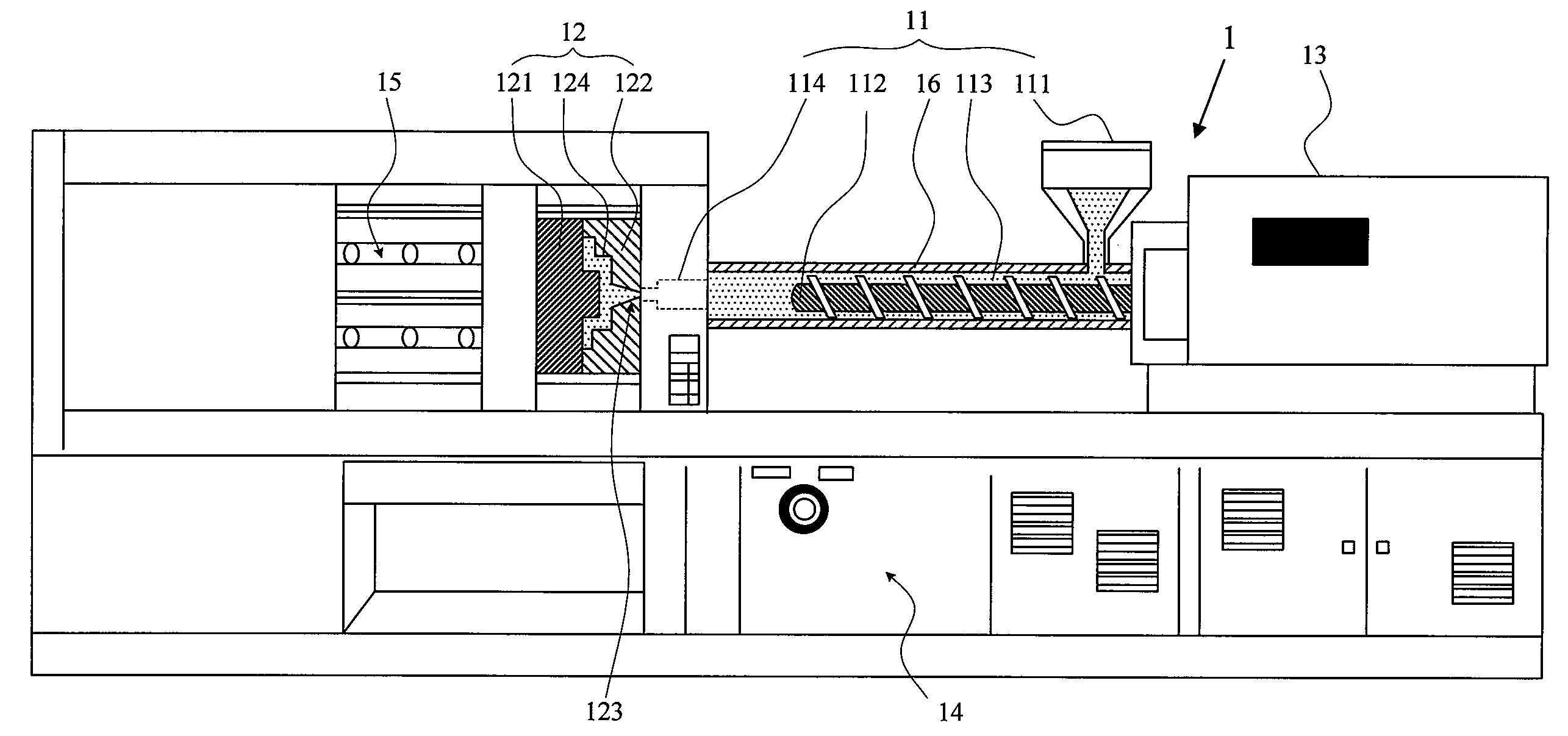
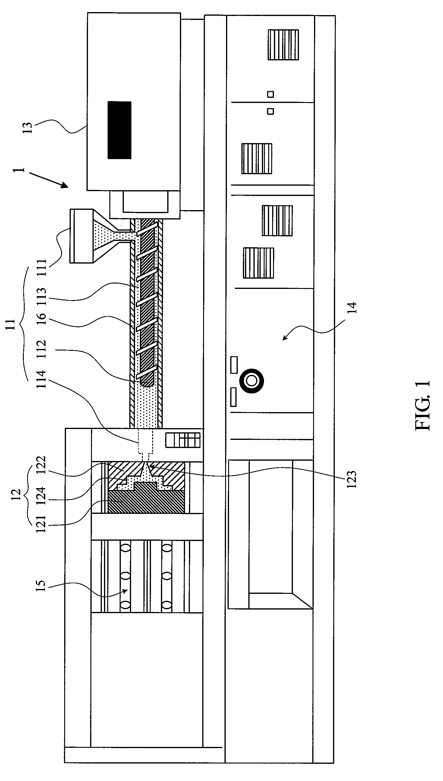
[0024]FIG. 1 is a schematic diagram showing an injection molding machine according to a preferred embodiment of the invention. Please refer to FIG. 1. In the embodiment, an oil hydraulic injection molding machine is taken for example. The injection molding machine 1 in the embodiment includes an injection system 11, a mold system 12, an oil hydraulic system 13, a control system 14, a clamping system 15, and a heat-insulating structure 16.

[0025]The control system 14 controls the whole molding operation in cooperation with plastic injection conditions and process analyses of the injection molding machine 1.

[0026]The clamping system 15 is responsible for a mold closing action and a mold opening action of the injection molding machine 1.

[0027]In the embodiment, the injection system 11 includes a hopper 111, a reciprocating screw 112, a barrel 113, and a nozzle 114.

[0028]The mold system 12 is disposed between the injection system 11 and the clamping system 15. In the embodiment, the mold...


PUM

PropertyMeasurementUnit
surface temperatureaaaaaaaaaa
temperatureaaaaaaaaaa
thicknessaaaaaaaaaa

Abstract

This invention discloses an injection molding machine and a heat-insulating structure of a barrel thereof. The heat-insulating structure covers the barrel of the injection molding machine. The heat-insulating structure includes a plurality of heat-insulating units and a plurality of heat-resistant interlinings. The heat-insulating units are disposed on an outer surface of the barrel in turn along an axial direction of the barrel. The heat-resistant interlinings are located between the heat-insulating units and connect the heat-insulating units, respectively. Each heat-insulating unit includes a heat-resistant layer, a heat-insulating material layer, and an insulating layer in turn. The heat-resistant layer covers the outer surface of the barrel of the injection molding machine.

Description

CROSS-REFERENCE TO RELATED APPLICATIONS[0001]This Non-provisional application claims priority under 35 U.S.C. §119(a) on Patent Application No. 097129388 filed in Taiwan, Republic of China, the entire contents of which are hereby incorporated by reference.BACKGROUND OF THE INVENTION[0002]1. Field of the Invention[0003]The invention relates to a heat-insulating structure and, more particularly, to an injection molding machine and a heat-insulating structure of a barrel thereof.[0004]2. Description of the Related Art[0005]In plastic manufacturing industry, injection molding is the most common manufacturing method. Generally, plastic is mixed and melted, and then the plastic is pressed and injected into a mold via a barrel.[0006]The barrel is a main heat generating region in an injection molding machine, and a surface temperature of the barrel generally can reach 200° F. However, in a conventional injection molding machine, the barrel is exposed to an operation environment. Therefore, ...

Claims


Application Information

Patent Timeline
Patent Type & Authority Patents(United States)
IPC IPC(8): B29C45/74
CPCB29C45/62
Inventor YU, CHIU-TINGWU, HSIEN-CHIHWU, YU-XIUJIANG, BO-TAOHSU, SHIH-CHI
Owner MINGSHUO COMP (SUZHOU) CO LTD
Why Eureka
Try Eureka