Multi-layer magnet arrangement in a permanent magnet machine for a motorized vehicle

a permanent magnet machine and multi-layer technology, applied in the direction of rotating magnets, synchronous machines with stationary armatures, magnetic circuits characterised by magnetic materials, etc., can solve the problems of demagnetization of permanent magnet motors and magnet strength reduction, and achieve the effect of lowering high-temperature stability and magnet strength

Inactive Publication Date: 2010-12-07
GM GLOBAL TECH OPERATIONS LLC
View PDF28 Cites 16 Cited by
  • Summary
  • Abstract
  • Description
  • Claims
  • Application Information

AI Technical Summary

Benefits of technology

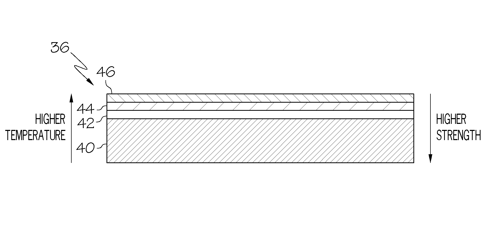
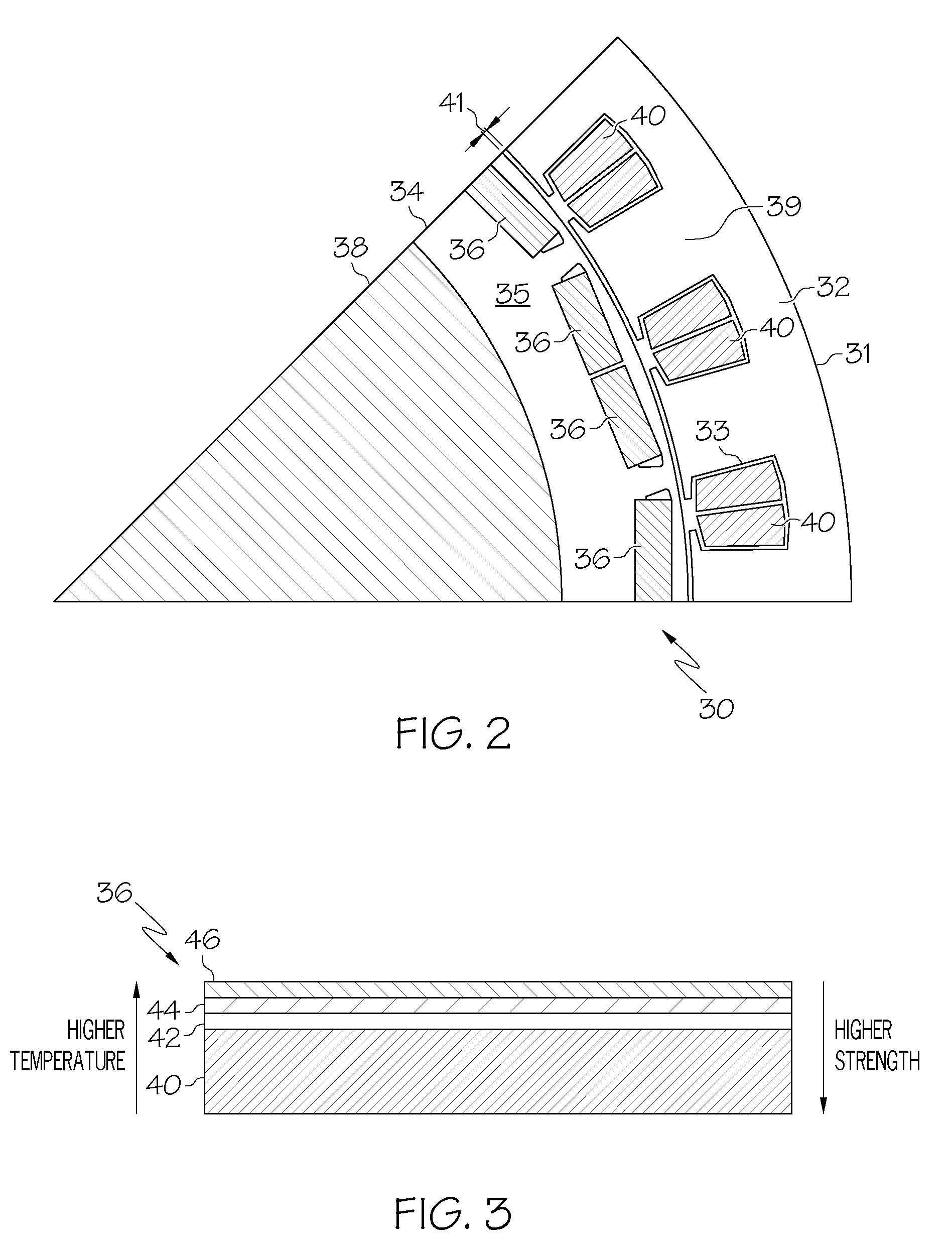
[0009]According to one embodiment of the invention, a permanent magnet machine is provided that includes a stator having a hollow core, a rotor rotatably disposed inside the hollow core, and a plurality of multilayered permanent magnets embedded in the rotor. Each multilayered permanent magnet has opposite first and second ends, and includes a first magnet disposed at the first end, and a second magnet disposed at the second end and coupled to the first magnet. The second magnet has higher magnet strength than the first magnet, and also has lower high-temperature stability than the first magnet.
[0010]According to another embodiment of the invention, a permanent magnet for a permanent magnet machine is provided. The permanent magnet has opposite first and second ends, and includes a first magnet disposed at the first end, and a second magnet disposed at the second end and coupled to the first magnet. The second magnet has higher magnet strength than the first magnet, and also has lower high-temperature stability than the first magnet.

Problems solved by technology

Elevated operating temperature environments for permanent magnet motors in automobiles, and particularly for hybrid applications, along with a high demagnification field that exists during machine operation, makes the permanent magnet motors vulnerable to demagnetization.
However, for high energy rare earth magnets such as neodymium iron boron or samarium cobalt magnets, the magnet strength reduces as the operational temperature increases.

Method used


Image

  • Multi-layer magnet arrangement in a permanent magnet machine for a motorized vehicle
  • Multi-layer magnet arrangement in a permanent magnet machine for a motorized vehicle
  • Multi-layer magnet arrangement in a permanent magnet machine for a motorized vehicle

Examples


Embodiment Construction

[0019]The following detailed description is merely exemplary in nature and is not intended to limit the invention or the application and uses of the invention. Furthermore, there is no intention to be bound by any expressed or implied theory presented in the preceding technical field, background, brief summary or the following detailed description.

[0020]Turning now to FIG. 2, a partial cross-sectional view is depicted of an embedded permanent magnet machine 30, which may be a component of various automobile components such as a transmission of a hybrid vehicle or a traction system for a fuel cell electric or purely electric vehicle. The permanent magnet machine 30 may also be used in high temperature applications unrelated to motor vehicles. Embodiments that incorporate the principles of the invention include both embedded and surface-mounted permanent magnet machines, of either the concentrated or distributed winding variety. Furthermore, an inside out machine in which the rotor is...


PUM


Abstract

A permanent magnet machine includes a stator having a hollow core, a rotor rotatably disposed inside the hollow core, and a plurality of multilayered permanent magnets embedded in the rotor. Each multilayered permanent magnet has opposite first and second ends, and includes a first magnet disposed at the first end, and a second magnet disposed at the second end and coupled to the first magnet. The second magnet has higher magnet strength than the first magnet, and also has lower high-temperature stability than the first magnet.

Description

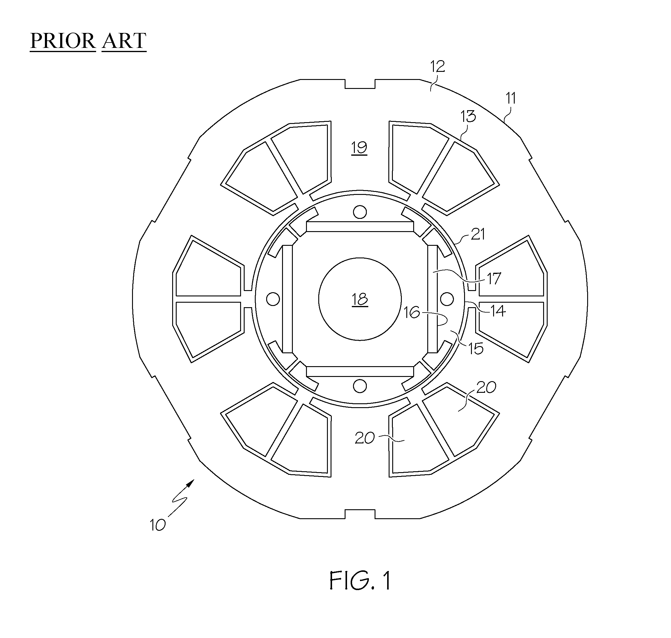
TECHNICAL FIELD[0001]The present invention generally relates to permanent magnet machines used in motors, and more particularly relates to motorized vehicles that incorporate permanent magnet machines.BACKGROUND OF THE INVENTION[0002]A permanent magnet machine includes a rotor having a core that supports mounted permanent magnets. The rotor is surrounded by a stator that includes static coils. Interaction of a winding magneto motive force, (MMF) produced by the static coils, with the permanent magnets generates a rotary driving force. Based on how the permanent magnets are mounted, permanent magnet motors are classified as either surface-mounted permanent magnet motors or embedded permanent magnet motors. The embedded permanent magnet motor includes a plurality of permanent magnets mounted in the rotor core, while the surface-mounted permanent magnet motor includes permanent magnets mounted on the rotor core surface. The embedded permanent magnet motor is consequently used when high...

Claims


Application Information

Patent Timeline
Patent Type & Authority Patents(United States)
IPC IPC(8): H02K21/12
CPCH02K1/276H02K1/2766H02K1/02
Inventor RAHMAN, KHWAJA M.KAISER, EDWARD L.LABA, MATTHEW D.
Owner GM GLOBAL TECH OPERATIONS LLC
Why Eureka
Try Eureka