Driving control apparatus and method, and exposure apparatus

a technology of driving control and control apparatus, applied in the direction of electric controllers, printers, instruments, etc., can solve problems such as nonlinear output errors, and achieve the effect of accurate driving control of an object and reducing the influence of sensor measurement errors

Inactive Publication Date: 2010-12-14
CANON KK
View PDF26 Cites 2 Cited by
  • Summary
  • Abstract
  • Description
  • Claims
  • Application Information

AI Technical Summary

Benefits of technology

[0007]The present invention has been made to overcome the above drawbacks, and has as its object to reduce the influence of a sensor measurement error and to implement accurate driving control of an object in controlling to drive the object.

Problems solved by technology

An error which makes the output nonlinear may occur also when the actual displacement of an object is a linear change.

Method used


Image

  • Driving control apparatus and method, and exposure apparatus
  • Driving control apparatus and method, and exposure apparatus
  • Driving control apparatus and method, and exposure apparatus

Examples


first embodiment

[0025]FIG. 11 is a schematic view showing the schematic arrangement of an exposure apparatus according to the first embodiment. In FIG. 11, a reticle 111 held on a reticle stage 102 is irradiated with exposure light emitted by an illumination unit 101. Exposure light having passed through the reticle 111 enters a projection optical system 103. The projection optical system 103 reduces, at a predetermined magnification, a pattern image formed by exposure light having passed through the reticle 111, and the reduced pattern image is projected onto a wafer 112 held by a wafer stage 1. The wafer stage 1 two-dimensionally moves on a surface plate 104.

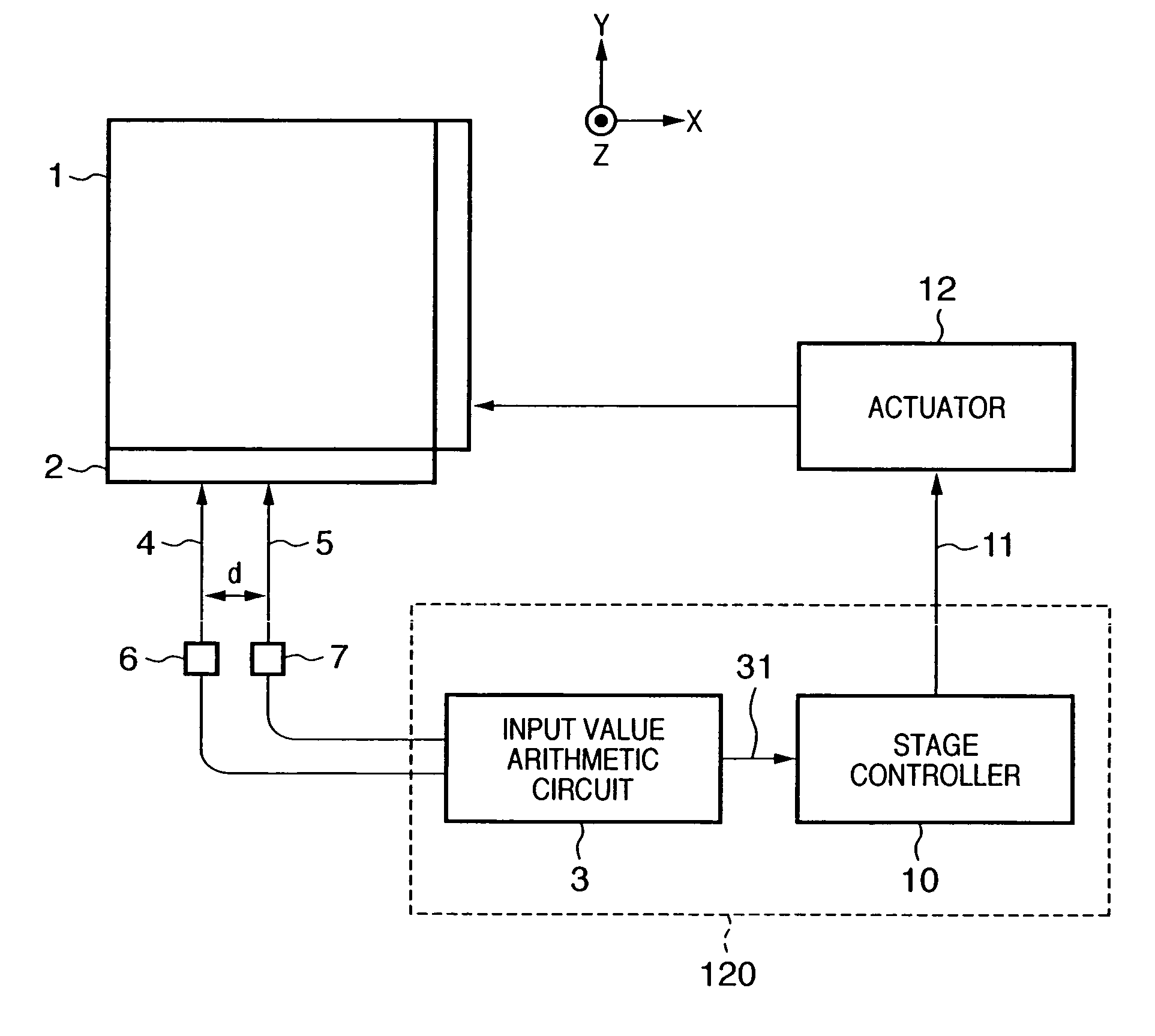
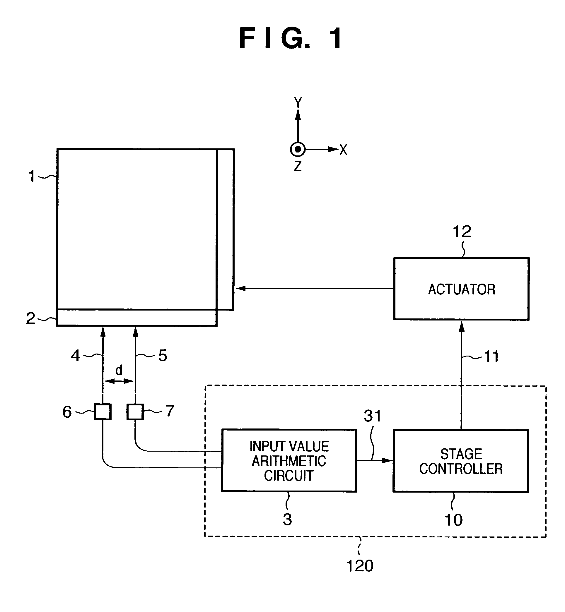
[0026]The position of the wafer stage 1 is measured by laser interferometers 6 and 7, and the like, and measurement values are input to a control unit 120. The control unit 120 outputs a drive signal to an actuator 12 so as to drive the stage to a target position on the basis of the input measurement values. The actuator 12 controls to drive ...

second embodiment

[0040]The average value of measurement values from an interferometer is calculated in the first embodiment, but the average value of rotation amounts may be calculated.

[0041]FIG. 7 is a block diagram showing the arrangement of an input value arithmetic circuit 3 according to the second embodiment. The measurement values of interferometers 7 and 6 are input to a subtractor 92. The subtractor 92 calculates the difference between the input measurement values, and outputs the difference value. Similar to the first embodiment, a plurality of measurement values is acquired by the interferometers 6 and 7 during one control cycle (during the measurement timing of each control cycle), and a plurality of difference values are output from the subtractor 92. An average value calculator 83 averages these difference values, and inputs the average value to a rotation amount arithmetic unit 93. The rotation amount arithmetic unit 93 converts the input difference value into a rotation amount 31 by u...

third embodiment

[0045]The rotation amount calculated in the first and second embodiments may be given an arbitrary offset. FIG. 9 shows this state. The offset is used to correct the rotation amount when the rotation amount has a predetermined offset from a true value upon averaging owing to the output characteristic of a sensor.


PUM


Abstract

A driving control apparatus for driving a controlled object. The apparatus includes first and second interferometers, each of which (i) detects a position of the controlled object in a predetermined direction and (ii) produces a respective detection value. A control unit obtains a rotation amount of the controlled object based on the detection values produced by the first and second interferometers, at a predetermined measurement timing, to calculate a controlled variable based on the rotation amount and a target value, and to output the controlled variable. A generation unit generates the rotation amount based on a difference value between two average values, one being an average value of detection values that are obtained by the first interferometer between a first measurement timing and a second measurement timing, immediately after the first measurement timing, and the other being an average value of detection values that are obtained by the second interferometer between the first measurement timing and the second measurement timing. The generation unit outputs the generated rotation amount to the control unit at the second measurement timing.

Description

FIELD OF THE INVENTION[0001]The present invention relates to a driving control apparatus, which measures the position of an object, or the like, and controls the position, rotation, and velocity of the object, or the like, on the basis of the measured value.BACKGROUND OF THE INVENTION[0002]To control an object to an arbitrary position or an arbitrary rotation, or to control to drive an object at an arbitrary velocity, the position of the object is measured by a sensor, and driving of the object is controlled on the basis of the measurement value.[0003]For example, a semiconductor exposure apparatus comprises a stage which supports a wafer to be exposed to a pattern and can be driven at an arbitrary position, rotation, and velocity. A position measurement sensor for this stage is a laser interferometer (see, e.g., Japanese Patent Laid-Open No. 2002-319541). The current position, rotation, and velocity of the stage are calculated on the basis of the measurement value of the laser inte...

Claims


Application Information

Patent Timeline
Patent Type & Authority Patents(United States)
IPC IPC(8): G05B11/32G03B27/58G05D3/12
CPCG03B27/58G03F7/70725
Inventor MATSUI, TAKAYASU
Owner CANON KK
Why Eureka
Try Eureka