Electrostatically atomizing device

a technology of atomizing device and atomizing coil, which is applied in the direction of air humidification system, lighting and heating apparatus, heating types, etc., can solve the problems of difficult supply of air flow of fan towards the atomizing device, and achieve the effects of improving heat radiation, stable operation, and promoting heat radiation of the heat exchanger

Inactive Publication Date: 2010-12-21
MATSUSHITA ELECTRIC WORKS LTD
View PDF16 Cites 9 Cited by
  • Summary
  • Abstract
  • Description
  • Claims
  • Application Information

AI Technical Summary

Benefits of technology

[0006]The electrostatically atomizing device in accordance with the present invention includes a housing and an electrostatically atomizing unit accommodated within the housing. The electrostatically atomizing unit includes an emitter electrode, an opposed electrode disposed in opposite relation to the emitter electrode, water supply means configured to supply water to the emitter electrode; and an atomizing barrel which surrounds the emitter electrode and is formed at its one axial end with a discharge port exposed to exterior of the housing. A high voltage source is disposed within the housing and is configured to apply a high voltage between the emitter electrode and the opposed electrode in order to electrostatically atomize the water supplied to emitter electrode for generating charged minute water particles and discharge the charged minute water particles through the opposed electrode out of the discharge port. The water supply means is composed of a heat exchanger having a cooling section and a heat radiator section. The emitter electrode is cooled by the cooling section to develop condensed water thereon. The housing includes a fan configured to generate a forced air flow of cooling the heat radiator section, and a straight flow passage which is configured to direct the forced air flow and to have the heat radiator section exposed therein. The atomizing barrel of the electrostatically atomizing unit is formed with an air inlet configured to introduce the air flow for carrying a mist of the charged minute water particles thereon and releasing it out of the housing. The electrostatically atomizing unit and the high voltage source are arranged on opposite sides of the flow passage. A first air intake port is provided to feed the forced air generated by the fan into the electrostatically atomizing unit, while a second air intake port is provided to feed the forced air flow into the flow passage. A third air intake port is provided to feed the forced air into the high voltage source. The first air intake port and the third air intake port are positioned upstream of the second air intake port. Because of that the electrostatically atomizing unit and the high voltage source are position on opposite sides of the flow passage of the air provided to cool the heat radiator section of the heat exchanger, and also because of that the air flow generated by the fan is supplied to the electrostatically atomizing unit and the high voltage source respectively through the first and third air intake ports both positioned upstream of the flow passage, it is realized to supply a non-heat exchanged fresh air to the electrostatically atomizing unit with an additional effect of promoting the heat radiation of the heat exchanger and cooling the high voltage source which is a heat source included in the housing, thereby assuring a stable generation of the mist of charged minute water particles without lessening the cooling effect of the emitter electrode.
[0007]Preferably, the housing is formed with a partition dividing an interior space of the housing into a first space and a second space. The first space receives therein the electrostatically atomizing unit and the fan, and is configured to form flow passage, while the second space receives therein the high voltage source, a rotation control circuit for controlling a rotation speed of the fan, and a temperature control circuit for controlling a cooling temperature of the heat exchanger. The third air intake port is formed in the partition. Thus, the rotation control circuit and the temperature control circuit can have improved heat radiation to be assured of stable operations.
[0008]Further, it is preferred that the housing has an exhaust port which is cooperative with the third air intake to define an air passage within the second space, and that a control module integrating the rotation control circuit and temperature control circuit is arrange along the air passage upstream of the high voltage source. With this arrangement, it is possible to thermally protect the rotation control circuit and the temperature control circuit from the high voltage source of large heat generating capacity, thereby assuring more stable operations.

Problems solved by technology

However, the prior electrostatically atomizing device is found difficult to supply the air flow of the fan towards the heat radiator section of the heat exchanger and the electrostatically atomizing unit individually or in a separate manner from each other.

Method used


Image

  • Electrostatically atomizing device
  • Electrostatically atomizing device
  • Electrostatically atomizing device

Examples


Embodiment Construction

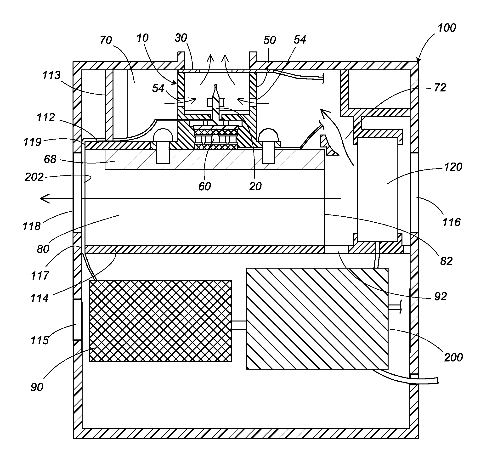
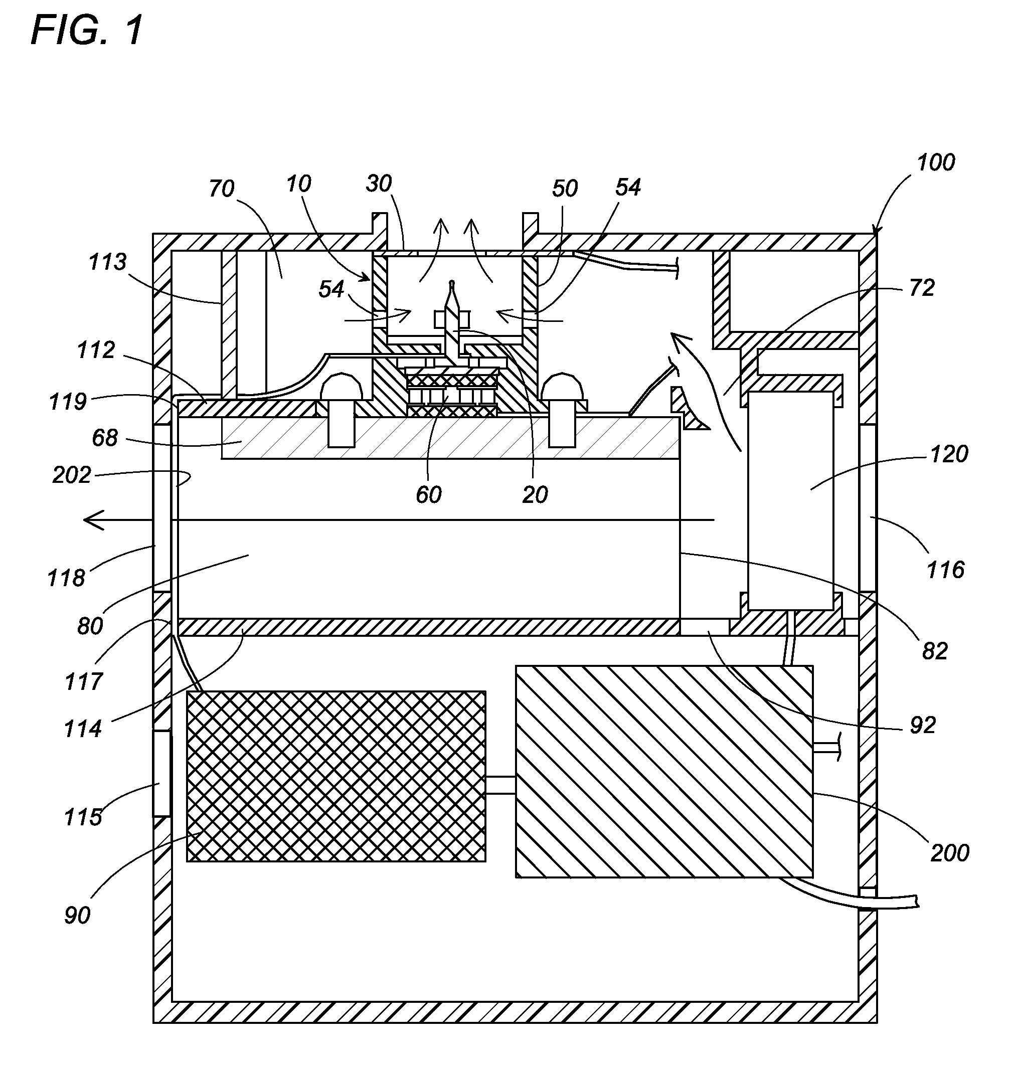
[0016]Now, a reference is made to the attached drawings to explain an electrostatically atomizing device in accordance with one embodiment of the present invention. As shown in FIG. 1, the electrostatically atomizing device includes an electrostatically atomizing unit 10 and a housing 100 accommodating the same. The housing 100 is composed, as shown in FIG. 4, of a case body 101 and a case lid 102 closing one face of the case body 101.

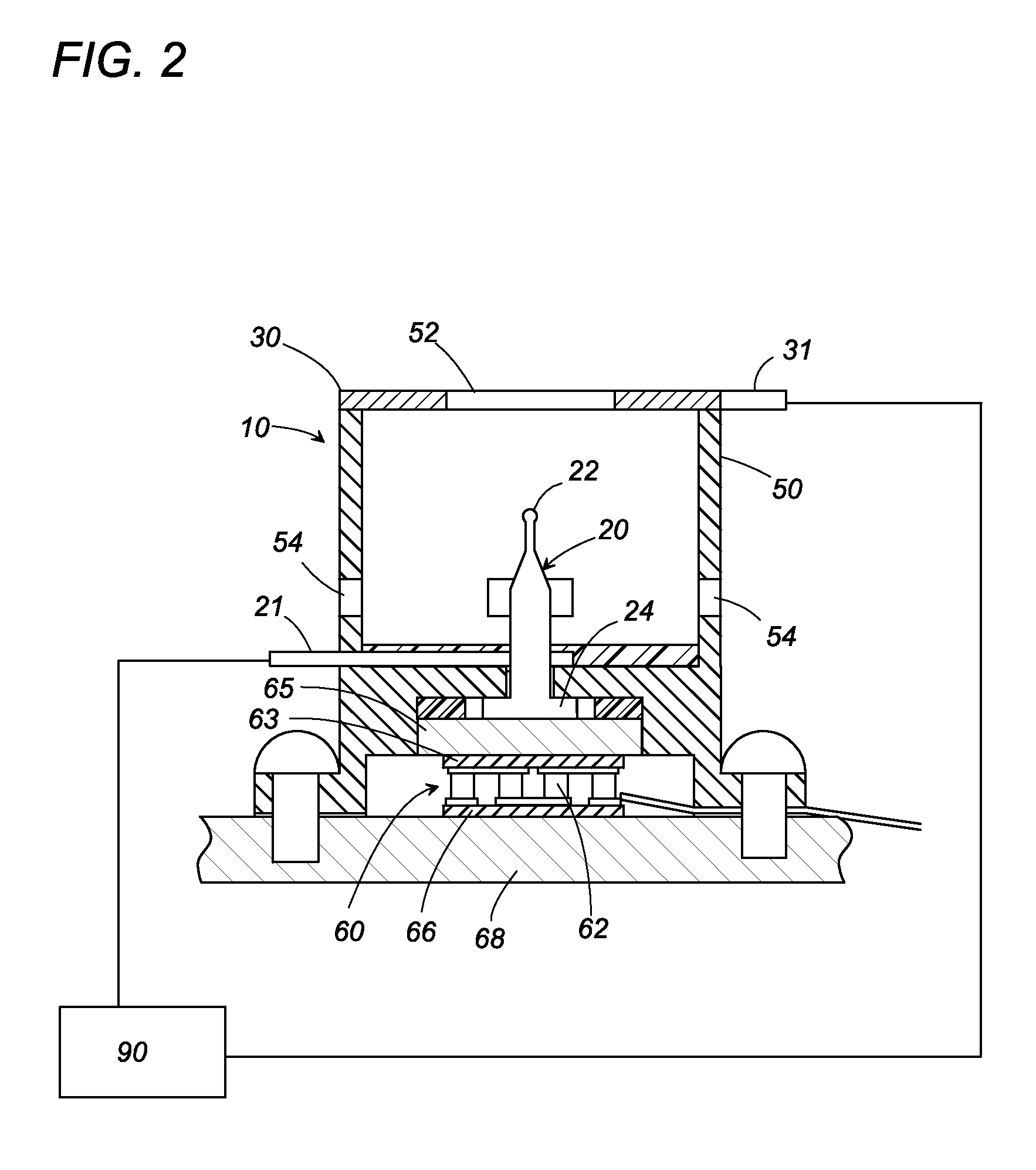
[0017]As best shown in FIG. 2, the electrostatically atomizing unit 10 includes an atomizing barrel 50 configured to hold an emitter electrode 20, an opposed electrode 30, and a heat exchanger 40. The emitter electrode 20 is disposed on a center axis of the atomizing barrel 50 to have its rear end fixed to a bottom wall 51 of the atomizing barrel 50 and to have its tip projecting into the atomizing barrel 50. The opposed electrode 30 is ring-shaped to have a center circular window and is fixed to the front end of the atomizing barrel 50 in an axially s...


PUM


Abstract

An electrostatically atomizing device includes a housing and an electrostatically atomizing unit disposed within the housing. The atomizing unit includes an emitter electrode and an heat exchanger. The heat exchanger cools the emitter electrode to develop condensed water. A high voltage is applied to the emitter electrode in order to electrostatically atomizing the condensed water and generate a mist of charged minute water particles. The housing accommodates a fan generating an air flow accelerating a heat radiation of the heat exchanger, and a high voltage source generating the high voltage applied to the emitter electrode. The heat exchanger has its heat radiator section exposed to a flow passage of the air flow. The atomizing unit is formed with an air inlet for introducing the air flow which carries the mist of the charged minute water particles and release the mist. The atomizing unit and the high voltage source are arranged on opposite sides of the flow passage. A first air intake port for feeding the forced air flow from the fan and a second air intake port for feeding the air flow into the high voltage source are positioned upstream of a second air intake port which introduce the forced air flow into the flow passage.

Description

TECHNICAL FIELD[0001]The present invention is directed to an electrostatically atomizing device of electrostatically atomizing water into a mist of minute charged water particles of nanometer sizes.[0002]As shown in international patent publication WO 2005 / 097339, an electrostatically atomizing device is known to electrostatically atomize water for generating a mist of charged minute particles of nanometer sizes. The electrostatically atomizing device has an emitter electrode, a water feed means for supplying the water to the emitter electrode, an atomizing barrel which defines an atomizing space in its interior and holds the emitter electrode in the space, and a high voltage applying section which applies a high voltage to the emitter electrode. With the high voltage applied to the emitter electrode, the water supplied on the emitter electrode is electrostatically atomized for generating the mist of charged minute particles of nanometer sizes.[0003]In the electrostatically atomizin...

Claims


Application Information

Patent Timeline
Patent Type & Authority Patents(United States)
IPC IPC(8): B05B5/00
CPCB05B5/001B05B5/03F24F6/12B05B5/0255B05B5/057B05B5/0533F24F6/14
Inventor YANO, TAKESHIHIRAI, TOSHIHISAHIRAI, LEGAL REPRESENTATIVE, KISHIKOWADA, SUMIOSUGAWA, AKIHIDEMATSUMOTO, TATSUHIKOAKISADA, SHOUSUKE
Owner MATSUSHITA ELECTRIC WORKS LTD
Why Eureka
Try Eureka