Apparatus and method for imaging the eye

a technology of eye and eye, applied in the field of eye imaging, can solve the problems of poor image quality, difficult alignment of devices, untrained staff, etc., and achieve the effects of reducing glare, eliminating artifacts and ghost reflections, and reducing glar

Active Publication Date: 2010-12-21
NEUROVISION IMAGING INC
View PDF3 Cites 55 Cited by
  • Summary
  • Abstract
  • Description
  • Claims
  • Application Information

AI Technical Summary

Problems solved by technology

Many comprehensive ophthalmologists and optometrists fail to fully utilize ophthalmic imaging devices (either traditional fundus cameras or imaging at the slit lamp) for a variety of reasons such as present day devices are expensive, image quality is poor, devices are difficult to align to a patient's eye, staff is not properly trained, images are not easily accessed, and overall device performance does not allow clinicians to realize the benefits and value of imaging.
While physicians would always prefer a widely dilated pupil for retinal examination, this is not always possible or convenient for patients.
Problems managing ghost and other reflections during examination, with undilated or dilated pupils, and lack of patient cooperation are common.
While there has been some market expansion to general ophthalmology and optometry of non-mydriatic fundus cameras, device expense, ease of access, and complexity of operation have hindered the widespread adoption of current devices.
Often these are separate free-standing devices that take up additional office space and are not convenient to the examination lane where primary eye exams are performed.
Although many practices place existing devices in patient test areas, they are not highly utilized for all the reasons previously stated.
Current slit lamp imaging systems are difficult to operate and do not eliminate specular reflections or other reflections from images.
Additionally, lighting is not easily controlled and is sub-optimal for retinal imaging over a wide field.
These devices can be difficult to align to a patient's pupil.
Additionally, some systems today utilize a point source for illumination, but their field-of-view of the retina is severely limited, optical artifacts are often present, can be difficult to eliminate, and image quality is generally poor.
Other systems use scanning laser systems which are expensive, and do not offer color imaging modes.
Some scanning laser systems also suffer from central artifacts and other reflections.

Method used


Image

  • Apparatus and method for imaging the eye
  • Apparatus and method for imaging the eye
  • Apparatus and method for imaging the eye

Examples


Embodiment Construction

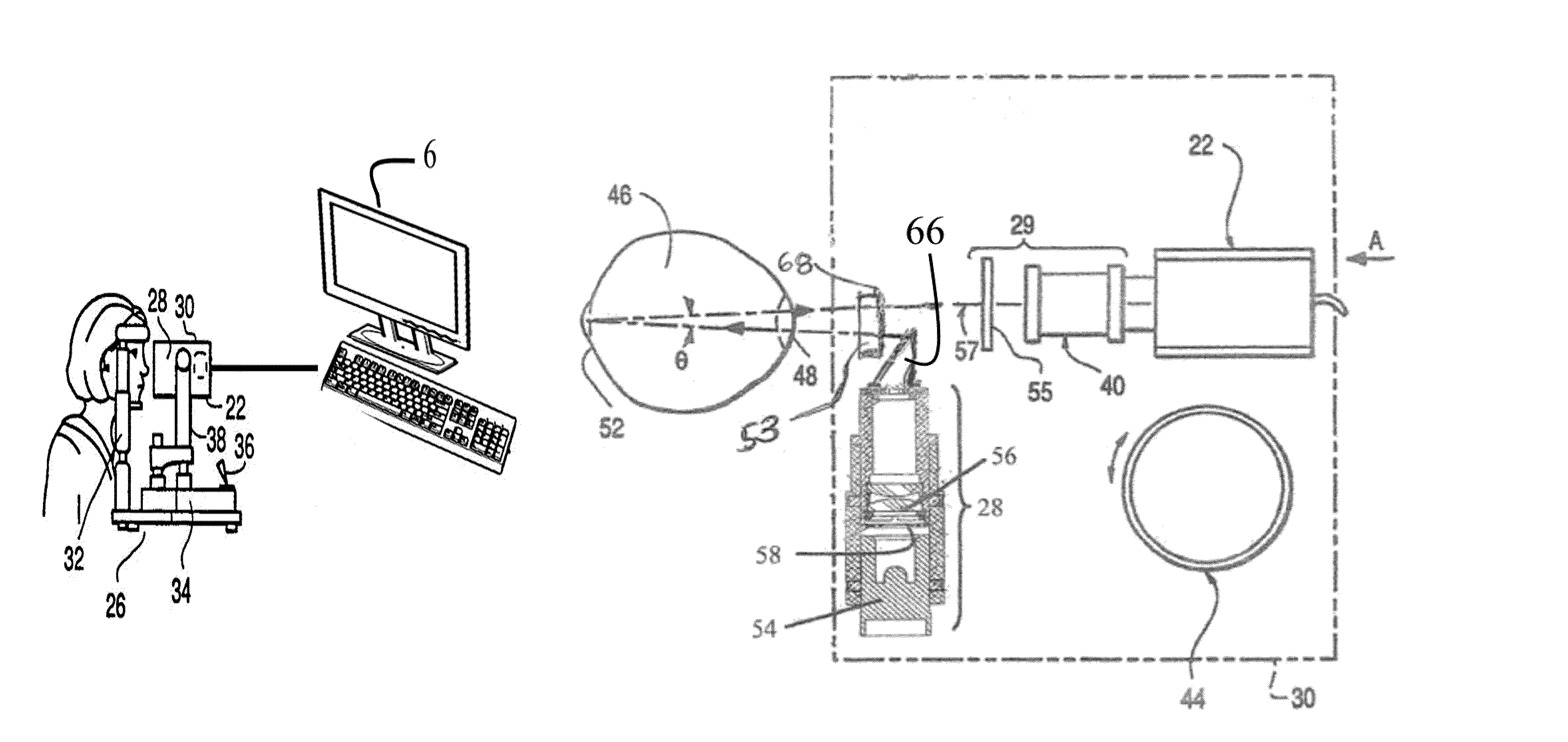
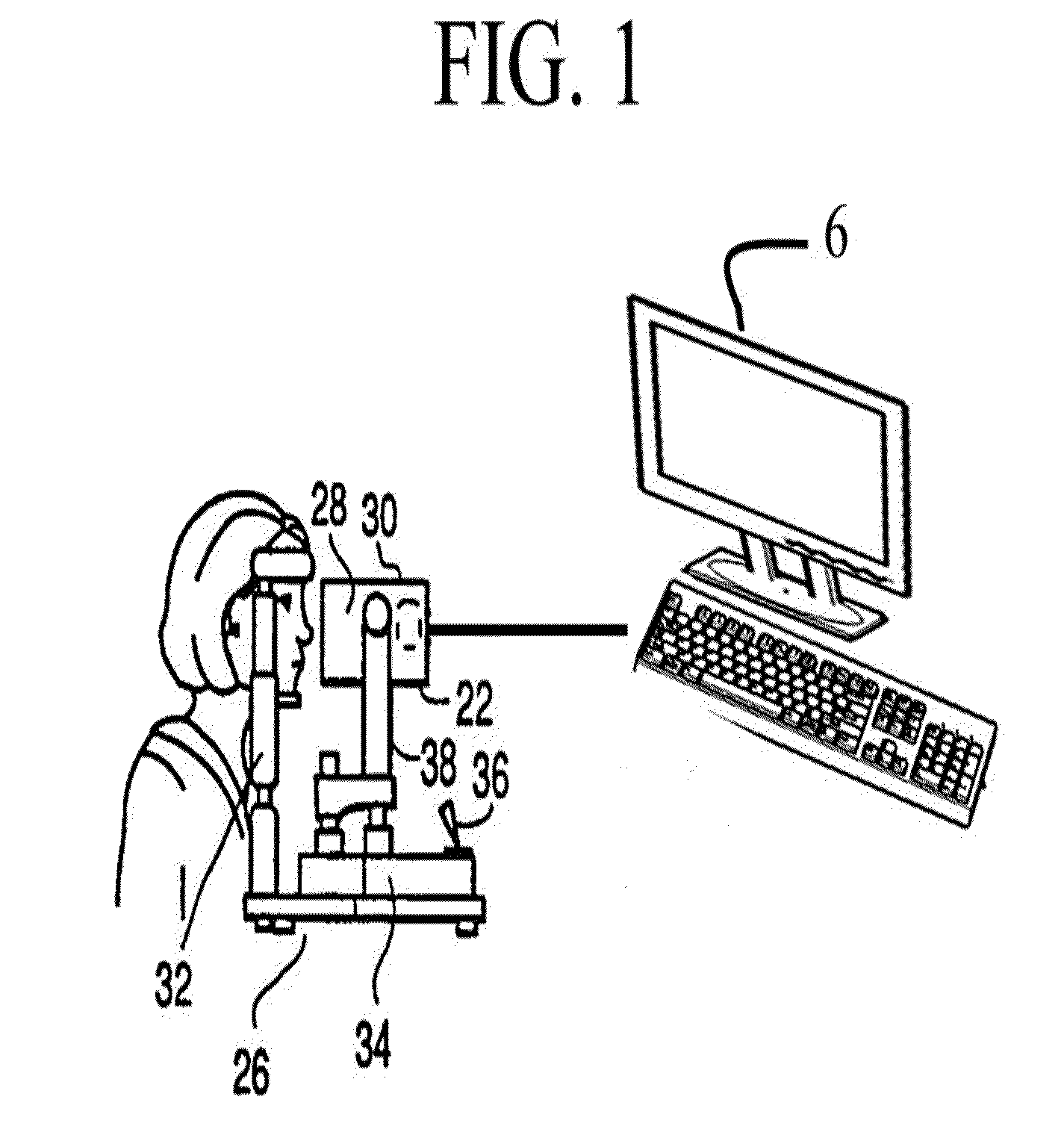
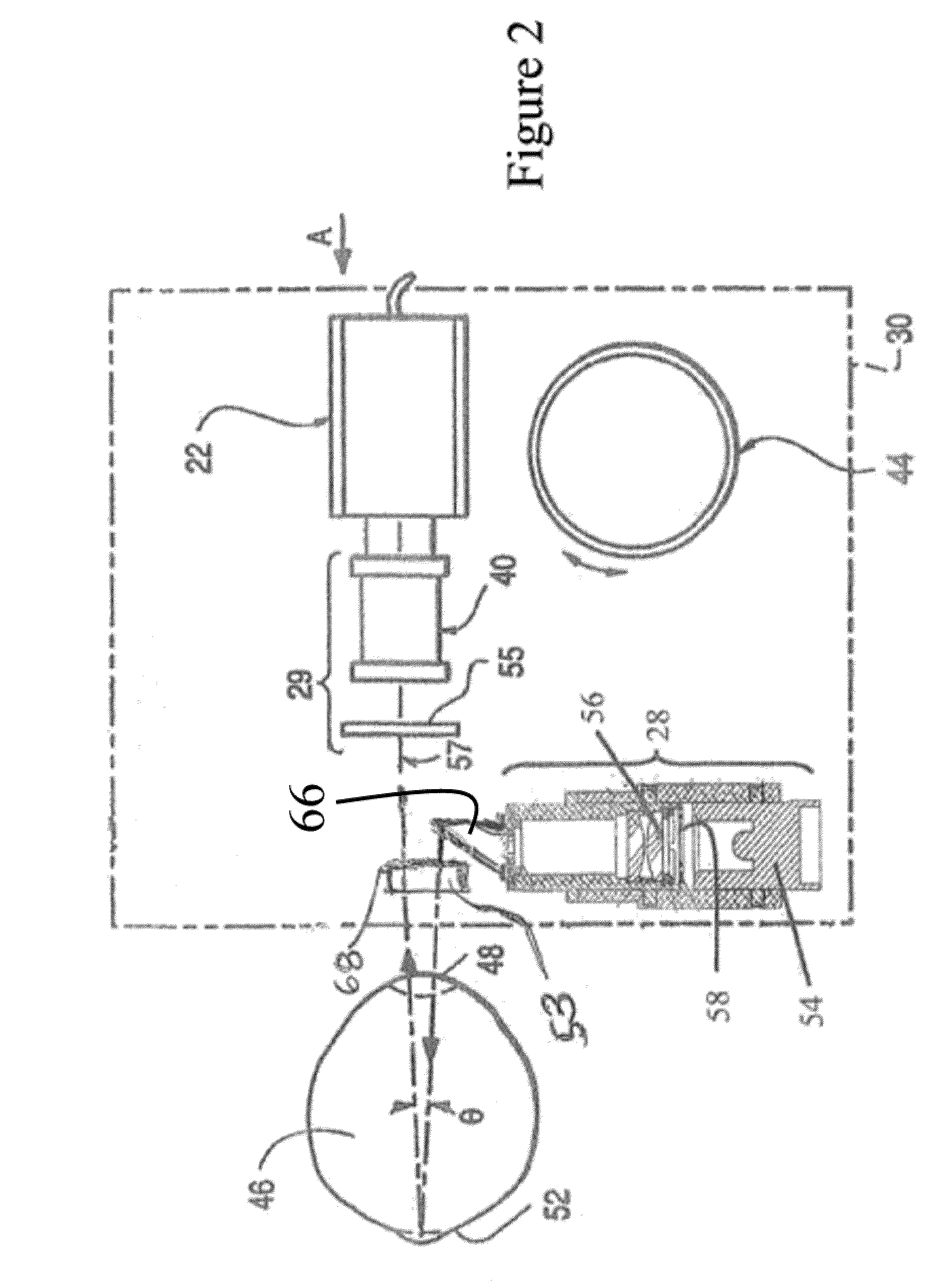
[0017]Retinal imaging has been traditionally performed with a fundus camera which uses an annulus of light to illuminate the retina, with the return image path coming back through the center of the illumination annulus. These devices often have complex illumination and imaging paths in order to allow the annulus to be as small as possible to accommodate a small pupil, while leaving ample aperture for imaging to pass back through the center, and to eliminate optical artifacts and reflections. This historical optical design was used to allow wider field imaging without reflections from the cornea and other surfaces. Traditional ophthalmoscopy (direct, indirect, slit lamp based or other) which have been based on a point source of illumination offer limited field of view if reflection-free images are desired. Retinal imaging systems based on point sources of light historically have only achieved a maximum of approximately thirty degree field of view, while still eliminating reflection a...


PUM


Abstract

A slit lamp mounted eye imaging device for viewing wide field and / or magnified views of the retina or the anterior segment through an undilated or dilated pupil. The apparatus images posterior and anterior segments of the eye, and sections / focal planes in between and contains an illumination system that uses one or more LEDs, shifting optical elements, and / or aperture stops where the light can be delivered into the optical system on optical axis or off axis from center of optical system and return imaging path from the retina, thereby creating artifacts in different locations on retina. Image processing is employed to detect and eliminate artifacts from images. The device is well suited for retinal imaging through an undilated pupil, non-pharmacologically dilated, or a pupil as small as 2 mm. Two or more images with reflection artifacts can be created and subsequently recombined through image processing into a composite artifact-free image.

Description

REFERENCE TO RELATED APPLICATIONS[0001]This patent application claims the benefit of U.S. Provisional Application No. 61 / 105,901 filed on Oct. 16, 2008, the disclosure of which is incorporated herein in its entirety by reference.[0002]A portion of the disclosure of this patent document contains material which is subject to copyright protection. The copyright owner has no objection to the facsimile reproduction by anyone of the patent document or the patent disclosure, as it appears in the Patent and Trademark Office patent file or records, but otherwise reserves all copyright rights whatsoever.BACKGROUND OF THE INVENTION[0003]1. Field of the Invention[0004]The present invention relates generally to imaging a person's eye and more specifically to imaging the anterior segment including the cornea, lens and anterior chamber of the eye, the posterior segment of the eye including the ocular fundus for imaging modalities such as color fundus, fluorescein angiography, ICG angiography, red-...

Claims


Application Information

Patent Timeline
Patent Type & Authority Patents(United States)
IPC IPC(8): A61B3/10A61B3/14
CPCA61B3/0083A61B3/12A61B3/117A61B3/1241A61B3/14A61B3/00A61B3/18
Inventor VERDOONER, STEVEN ROGERLEACH, STEVEN
Owner NEUROVISION IMAGING INC
Why Eureka
Try Eureka