Automatic gain control for fiber optic gyroscope deterministic control loops

a fiber optic gyroscope and control loop technology, applied in the direction of speed measurement using gyroscopic effects, instruments, surveying and navigation, etc., can solve the problems of fiber optic gyro as a rotation sensor operation, large dither residual, saturation of the front end of the gyro control loop

Active Publication Date: 2010-12-28
NOTHROP GRUMMAN GUIDANCE & ELECTRONICS CO
View PDF10 Cites 5 Cited by
  • Summary
  • Abstract
  • Description
  • Claims
  • Application Information

AI Technical Summary

Benefits of technology

[0003]This invention permits the use of a perturbation to measure fiber optic gyroscope loop gain error so that it may be stabilized and eliminates the perturbation signal from the output of the fiber optic gyroscope.
[0004]The present invention produces a demodulated gain error by filtering the fiber optic gyroscope loop output signal and a pilot reference signal with a high pass filter that eliminates low frequency true angular rate signals. Filtering the pilot signal and the fiber optic gyroscope output signal with the same filter ensures proper phase relationship between these signals. The filtered signals are multiplied together and integrated to provide a gain error signal. The gain error signal may be further filtered or multiplied by a gain attenuation factor to provide the desired automatic gain control time constant. The automatic gain control signal is fed back to a variable gain to stabilize the gain.

Problems solved by technology

If these conditions are not met, problems occur in operation of the fiber optic gyro as a rotation sensor.
The problems include saturation of the front end of the gyro control loop for large dither amplitudes due to the limited loop bandwidth and finite analog to digital converter input range and large dither residuals in the output if there are not precisely an integer number of dither cycles in the sampling period.
Saturation in the control loop leads to increased random walk through failure to cancel the dither signal and other undesirable nonlinearities.
Decreasing the amplitude of the dither signal to avoid saturation could result in there not being sufficient dither to break up the deadband at high sampling rates.

Method used


Image

  • Automatic gain control for fiber optic gyroscope deterministic control loops
  • Automatic gain control for fiber optic gyroscope deterministic control loops
  • Automatic gain control for fiber optic gyroscope deterministic control loops

Examples


Embodiment Construction

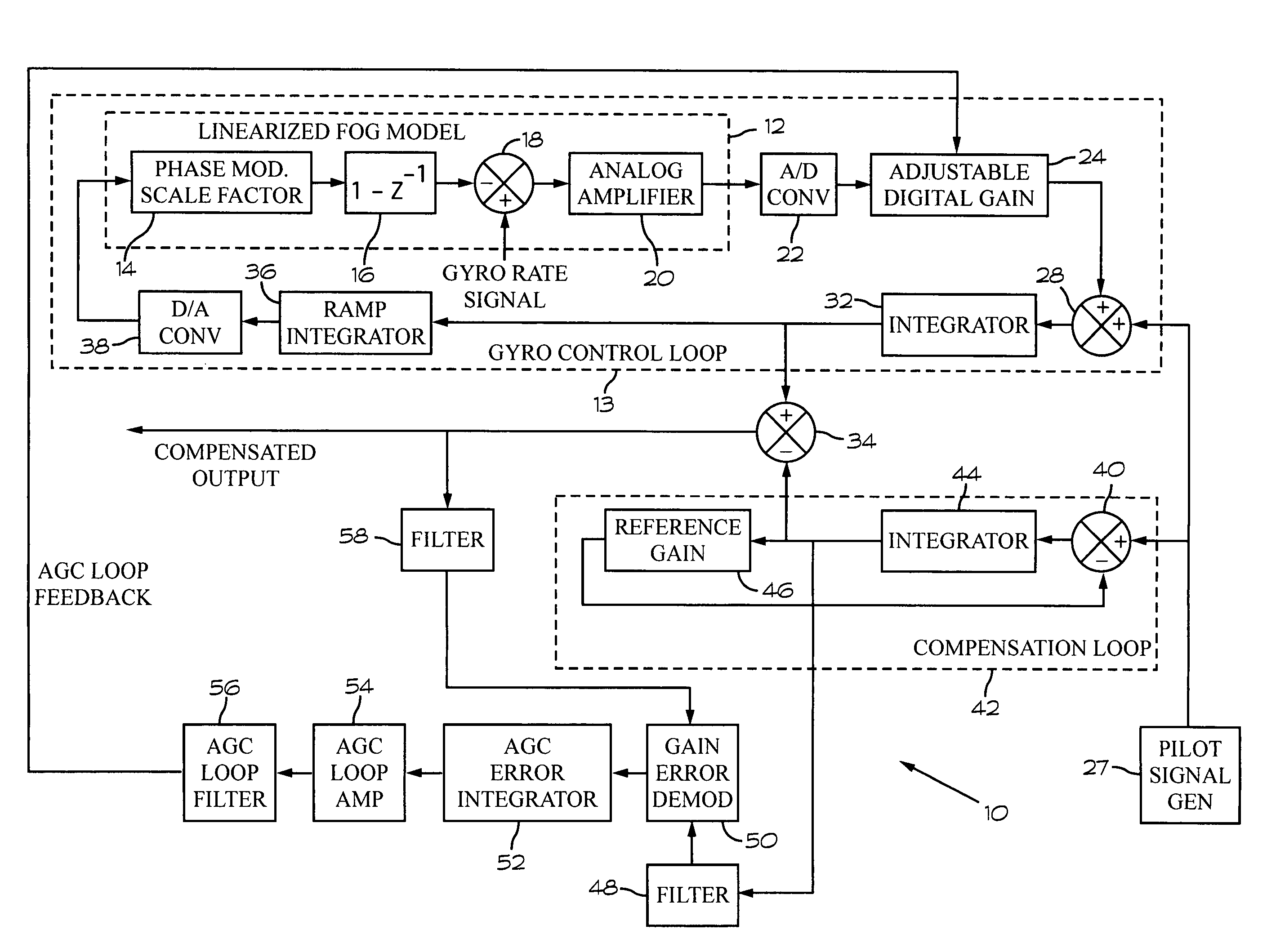
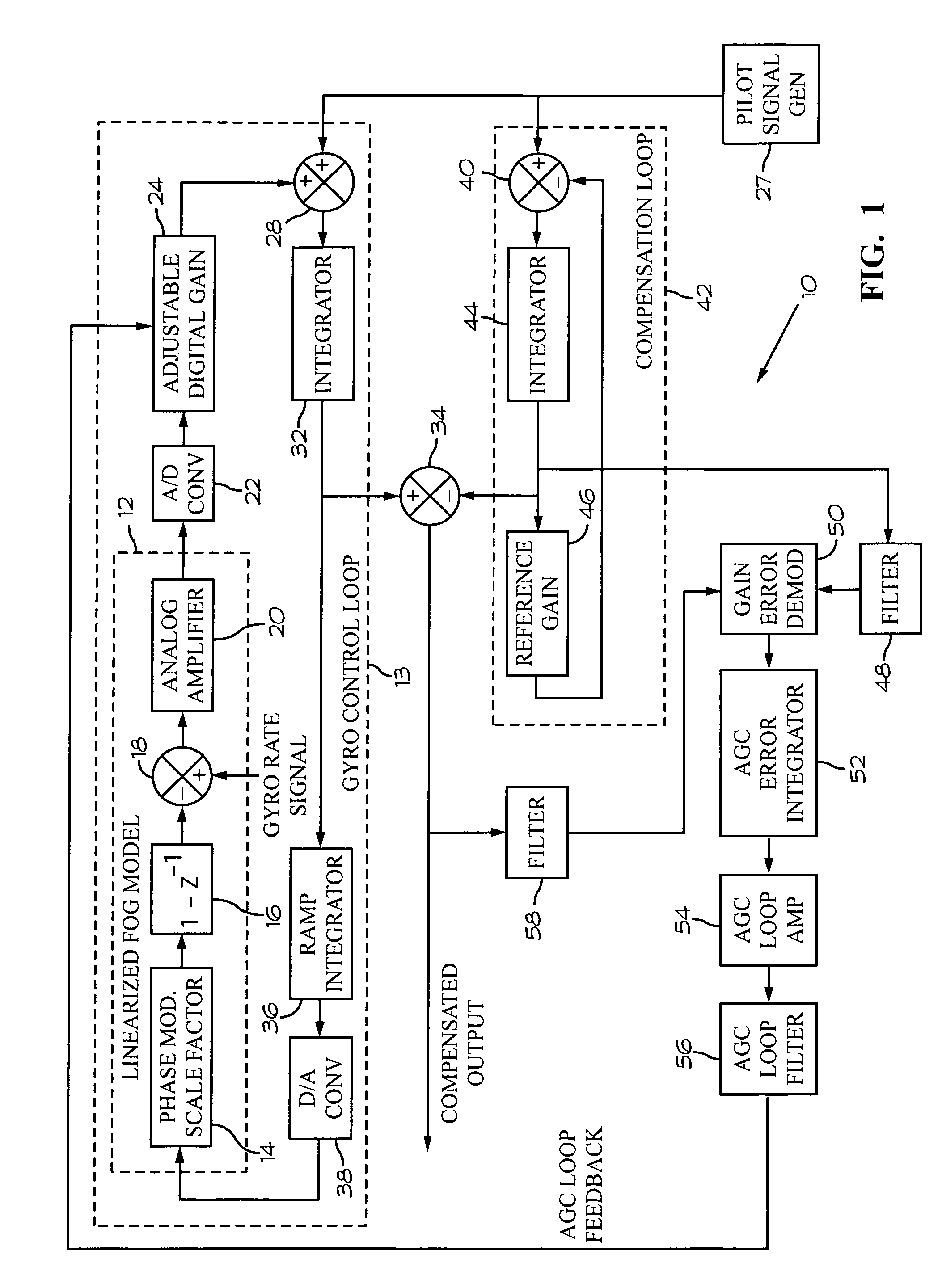
[0014]Referring to FIG. 1, an automatic gain control system 10 is shown connected to a linearized fiber optic gyroscope (FOG) model 12. The prior art includes descriptions of several fiber optic gyroscopes (not shown) that will function with the automatic gain control system 10. The linearized fiber optic gyroscope model 12 should be understood to represent any prior art fiber optic gyroscope.

[0015]The linearized fiber optic gyroscope model 12 includes a phase modulator 14 that has a selected scale factor. A control loop 13 forms the basis for a closed-loop fiber optic gyro. The output of the phase modulator 14 is input to the FOG 16, which is also connected to a summer 18. The summer 18 produces a signal output that is the difference of the signal input from FOG loop and the gyro rate signal. The output of the summer 18 is amplified by an analog amplifier 20 that has a selected gain. The amplified analog signal is then input to an analog to digital converter 22. The digital signal ...


PUM


Abstract

An automatic gain control system for a fiber optic gyroscope control loop includes an adjustable gain applied to the gyro output signal. A pilot signal is injected into the fiber optic gyroscope control loop. A compensation loop receives signals output from the control loop and also receives pilot signals. The compensation loop processes the pilot signal to produce a compensation signal that is combined with signals output from the control loop to provide a compensated fiber optic gyroscope output signal. An automatic gain control loop is connected between the compensation loop and the adjustable gain applied to the fiber optic gyroscope output signal. The automatic gain control loop includes a gain error demodulator that multiplies the compensated fiber optic gyroscope output signal and the compensation signal together to produce a gain error signal used to control the adjustable gain in order to stabilize the gain of the gyro control loop.

Description

BACKGROUND OF THE INVENTION[0001]This invention relates generally to fiber optic gyroscope rotation sensing systems. More particularly, this invention relates to the processing of signals output from a fiber optic gyroscope to measure rotation rates. Still more particularly, this invention relates to an improved electronic dither system and method using a low amplitude dither signal in a fiber optic gyroscope signal processing system.[0002]U.S. Pat. No. 5,020,912, which issued Jun. 4, 1991 to George A. Pavlath, one of the inventors of the present invention, discloses a deadband circumvention technique for a closed loop fiber gyro that uses deterministic phase modulation. A periodic zero mean dither signal is input to an integrator that also has the gyro demodulated rate signal as an input. A key requirement is that the gyro loop bandwidth be greater than the dither frequency, which in turn is larger than the sampling frequency. Ideally the dither frequency is at least ten times the ...

Claims


Application Information

Patent Timeline
Patent Type & Authority Patents(United States)
IPC IPC(8): G01C19/72
CPCG01C19/726
Inventor TAZARTES, DANIEL A.PAVLATH, GEORGE A.
Owner NOTHROP GRUMMAN GUIDANCE & ELECTRONICS CO
Why Eureka
Try Eureka