Imaging systems for ionising radiation

a technology of ionising radiation and imaging system, which is applied in radiation therapy, x-ray/gamma-ray/particle irradiation therapy, medical science, etc., can solve the problems of ionising the material of which they are formed, scintillation in the scintillator, and portal images suffering from artefacts,

Active Publication Date: 2010-12-28
ELEKTA AB
View PDF5 Cites 2 Cited by
  • Summary
  • Abstract
  • Description
  • Claims
  • Application Information

AI Technical Summary

Benefits of technology

[0011]The total time required for a treatment will ideally be minimised. As time passes, the patient tires and may move or involuntary internal motion may occur, meaning that long treatment times can be less clinically effective. Further, a reduced treatment time can allow more patients to be treated, thereby increasing the clinical efficiency of the apparatus. Thus, from the desire to deliver the treatment in the minimum possible time, it can be inferred that there must be a very good reason indeed for the adoption of a duty cycle as low as 0.1%. Even a duty cycle as low as 1% would allow a tenfold improvement in clinical efficiency together with an (unqualified) improvement in clinical effectiveness.
[0017]Typical systems today have a maximum pulse rate of 400 to 600 pulses per second. The use of the above-described invention can allow this pulse rate to be increased to 1000 or even 1500 pulses per second during the periods while pulses are being produced.

Problems solved by technology

We have found that such portal images suffer from artefacts that relate to the pulses of MV energy.
When a MV pulse arrives, it will not only cause scintillation in the scintillator, but will also impinge on the transistor array and the read-out electronics and ionise the material of which they are formed.

Method used


Image

  • Imaging systems for ionising radiation
  • Imaging systems for ionising radiation
  • Imaging systems for ionising radiation

Examples


Embodiment Construction

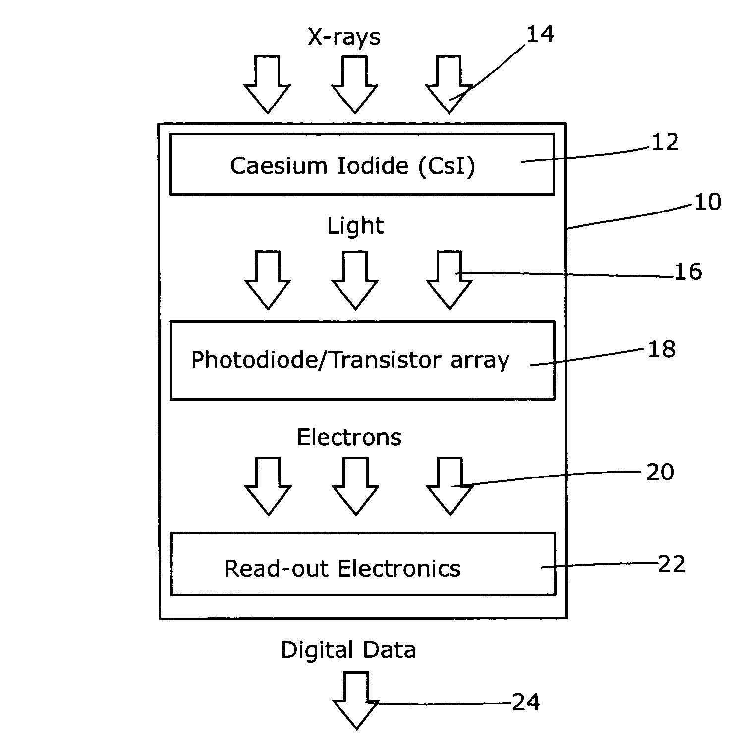
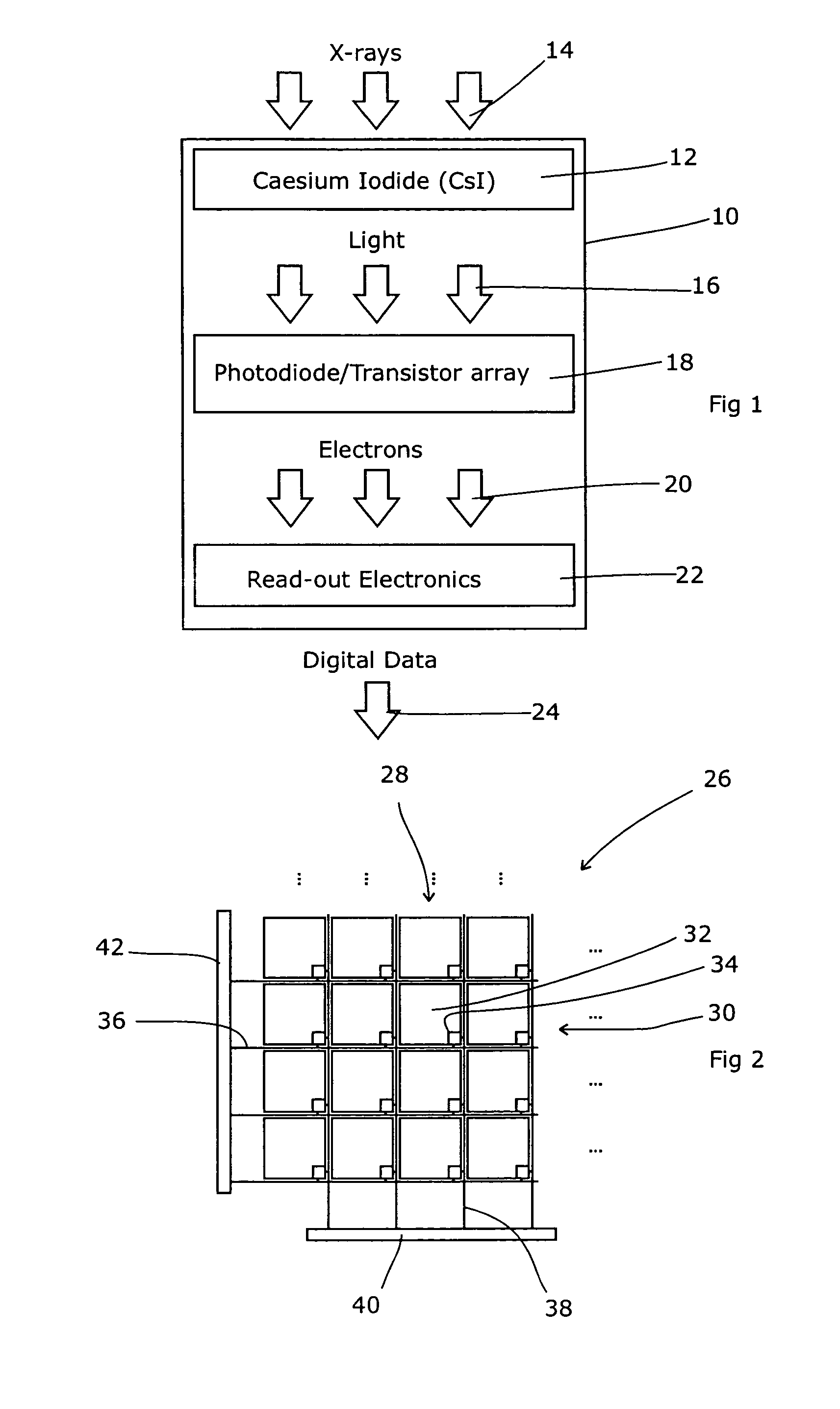
[0027]FIGS. 1 and 2 show an essentially standard imaging panel. FIG. 1 has been described already and shows the vertical cross-section through a single pixel. FIG. 2 shows sixteen pixels of the panel, a small portion of the entire panel but sufficient to explain the manner in which multiple pixels are read.

[0028]Referring to FIG. 2, therefore, the pixel array 26 is arranged in a rectilinear manner with the pixels in straight rows and columns. The intersection of a particular row 28 with a particular column 30 therefore defines a specific pixel 32. Each pixel has an associated transistor 34 to gate its output, and each row has a common “enable” line 36 which activates the transistor 34 of every pixel in that row.

[0029]Each column has a common output line 38 which allows the charge that has accumulated on each pixel to escape to an integrator 40 where it is multiplexed with the output of other columns. This allows the entire row to be read at the same time.

[0030]Scanning control elect...


PUM


Abstract

Flat panel images obtained during concurrent radiotherapy typically suffer from artefacts that relate to the pulses of MV energy. For a radiotherapeutic apparatus comprising a pulsed source of therapeutic radiation, a detector comprising control circuitry, an array of pixel elements, each having a signal output and an ‘enable’ input and being arranged to release a signal via the signal output upon being triggered by the enable input, and an interpreter arranged to receive the signal outputs of the pixel elements, the interpreter having a reset control, there are advantages in the control circuitry being adapted to reset the interpreter after a pulse of therapeutic radiation, prior to enabling at least one pixel of the array. Alternatively, the control circuitry can prompt a plurality of pulses by the pulsed source and then enable a plurality of pixels of the array. In effect, the therapeutic pulses are grouped into a short flurry of pulses. It is therefore preferred that the plurality of pixels comprises substantially all the pixels of the array.

Description

CROSS-REFERENCE TO RELATED APPLICATION[0001]This Application is a Section 371 National Stage Application of International Application No. PCT / EP2006 / 008905, filed Sep. 13, 2006 and published as WO 2008 / 031443 A1 on Mar. 20, 2008, the content of which is hereby incorporated by reference in its entirety.FIELD OF THE INVENTION[0002]The present invention relates to imaging systems for detecting ionising radiation.BACKGROUND ART[0003]Flat panel images are often used in radiotherapy and other applications in order to derive an image from ionising radiation that has (for example) passed through a patient. Diagnostic images are generally obtained from the use of kilovoltage (kV) radiation and can be used either as two dimensional images or can be used as one of a number of such two dimensional images in order to create three dimensional representations via computed tomography (CT). Therapeutic radiation tends to be in the megavoltage (MV) range and can also be used to derive a portal image....

Claims


Application Information

Patent Timeline
Patent Type & Authority Patents(United States)
IPC IPC(8): A61N5/10
CPCA61B6/032A61N5/1049A61B6/4488A61N2005/1054
Inventor LONG, ANDREWBROWN, KEVINALLEN, JOHN
Owner ELEKTA AB
Why Eureka
Try Eureka